Notice: This Wiki is now read only and edits are no longer possible. Please see: https://gitlab.eclipse.org/eclipsefdn/helpdesk/-/wikis/Wiki-shutdown-plan for the plan.
Difference between revisions of "Getting Started with Papyrus UMLLight"
(→Package Diagram: Added section to create the package diagram) |
(→Package Diagram: Added palette) |
||
| Line 382: | Line 382: | ||
== Package Diagram == | == Package Diagram == | ||
| + | |||
| + | [[File:PUL-Package-Palette.png|600px|right|]] | ||
| + | |||
:: Build a simple package diagram for a layered model development approach | :: Build a simple package diagram for a layered model development approach | ||
Revision as of 15:49, 7 May 2019
Getting Started with Papyrus UMLLight
Contents
- 1 Introduction
- 2 What are Papyrus and Papyrus UMLLight
- 3 Papyrus UMLLight Short User personae.
- 4 Papyrus UMLLight Full User personae.
- 5 Installing Papyrus UMLLight
- 6 Running Papyrus UMLLight
- 7 Palettes
- 8 Online Shopping System (OSS) Project Overview
- 9 Use Case Modeling
- 10 Modeling the OSS Use Case
- 11 Populate the OSS Use Case Diagram
- 12 Documentation View
- 13 Adding Structure to models
Introduction
As part of this tutorial, the trainee will:
- Learn how to download and install Papyrus UMLLight.
- Become familiar with the various aspects of the modeling environment such as workspaces, menus, views, perspectives and palettes.
- Become familiar with the elements that make up the“Papyrus UMLLight” subset.
- Through the implementation of a sample modeling project, become familiar with a simple model development approach that will enable you to use the elements that are part of the Papyrus UMLLight subset.
At the end of the training, the trainee will be able to apply their acquired knowledge in real project.
What this tutorial is and is not
| what this tutorial IS | What this tutorial Is NOT |
|---|---|
| An overview of the Papyrus UMLLightuser interface | A UML specification tutorial |
| An overview of the UML diagrams and elements available in Papyrus UMLLight | An exhaustive tutorial on all UML diagrams, entities, and semantics |
| An hands-on experience developing a UML model with Papyrus UMLLight | A tutorial advocating a specific method for modeling software, |
What are Papyrus and Papyrus UMLLight
What is Papyrus
- * A complete open Source editor that Conform to UML, SysML, and other Object Management Group (OMG) standards
- * [An Eclipse Project [1]
- A familly of modeling tools
- Papyrus itself (both tool and platform) ("Papyrus")
- * Papyrus for information modeling ("Papyrus-IM")
- * Papyrus for Real-time ("Papyrus-RT")
- * and now Papyrus UMLLight
- * [Supported by the Papyrus Industry Consortium, a community of developers, committers and contributors from many organizations and involved in different application domains.
What is Papyrus UMLLight
- * A specialized variant of Papyrus that provides:
- * * an optimized “Foundation level” subset of UML;
- :: * with a streamlined user interface for creating, viewing, and editing models
Comparing Papyrus and Papyrus UMLLight

Papyrus UMLLight Short User personae.
Discussions with various stakeholders, enabled the Papyrus UMLLight team to defined the following three user personae to express the needs Papyrus UMLLight's targeted users:
 * Nicole, a [Papyrus novice, is knowledgeable in UML but not familiar with Papyrus or Papyrus UMLLight
 * Steve - a UML Novice and Student, a student and novice in UML, Papyrus, and Papyrus UMLLight
 * Brisha, a Basic UML User, only uses UML from time to time and then only for basic purposes such as documentation or, presentations
Papyrus UMLLight Full User personae.
==
Nicole, a [Papyrus novice, is knowledgeable in UML but not familiar with Papyrus or Papyrus UMLLight
- Nicole is already knowledgeable in UML at or above the OCUP2 Foundation or intermediate level contents.
As the project on which ze worked was completed, ze is being moved to a new team that uses Papyrus, a tool with which ze is not familiar. Nicole's goal in using Papyrus UML Light is to quickly get familiar with Papyrus UML Light and how it supports UML-based modeling. Ze appreciates and benefits from Papyrus UML Light's streamlined editor with the most common concepts of UML, so that ze can focus on getting to know the Papyrus UML Light user interface and way of working without being exposed to the full spectrum of UML model elements.
==
Steve , a student and novice in UML, Papyrus, and Papyrus UMLLight
- Steve is new to the modeling world and has no or very limited familiarity with the UML. Steve is starting to learn about UML and faces the dual tasks of learning to use UML at the same time as learning to use a UML modeling tool.
Using Papyrus UML Light, Steve will be exposed to fewer language and tool concepts at a time, which results in a lowering of the learning curve. In addition, the alignment of Papyrus UML Light to OCUP2 (Foundational) is beneficial, as it ensures that ze first deals with the most most important concepts of UML before tackling the more complex aspects.
==
Brisha, A basic UML User.
- Brisha only uses UML from time to time and then only for basic purposes such as documentation or, presentations, discussions, etc. Ze is not interested in a full model-based engineering tool or method and rather uses it to "sketch" using UML to ensure common understanding of the graphics. As such, ze only needs the basic concepts of UML. In this context, an easy to use UML modeling tool such as Papyrus UML Light, which provides a reduced, targeted user interface and ease of use is easiest to adopt.
If you recognize yourself in one of these personae, this product is for you!
Installing Papyrus UMLLight
To install Papyrus UMLLight, follow these steps:
1. Ensure that you have Java 8 (or later) installed and configured for your operating system.
2. Go to: https://wiki.eclipse.org/Papyrus_UMLLight#Downloads
3. The list of downloads for different operating environments will be displayed:
- * Papyrus UML Light 0.0.1 RC2* for Windows 64bit
- * Papyrus UML Light 0.0.1 RC2* for Linux 64bit
- * Papyrus UML Light 0.0.1 RC2* for MacOS X 64bit
4. Click on the link for your development environment to download the archive
5. Extract the executable from the downloaded archive into the proper location for your operating system.
- Tip: On MacOS and some Linux, you may need to use “gunzip” followed by “tar xvf” to successfully extract the archive.
6. You are now ready to start using Papyrus UML Light!
Running Papyrus UMLLight
1. Double-click on the Papyrus UMLLight application you installed in the previous step.
2. A dialog is shown asking you to select a workspace.

About Workspaces
- Workspaces are folders on your computer where your models and associated files are stored.
1. Click on browse to select a folder that will hold your work.
2. Click “Launch” to start Papyrus UMLLight
3. The Papyrus UMLLight modeling environment's workspace is shown.


Palettes
- Palettes are the toolboxes of the Papyrus UMLLight modeling environment.
Palette Structure


Customized Palettes
In addition to the common tools, every Papyrus UMLLight diagram has a customized palette” containing the model elements that can be used with that diagram. You can think of it as your modeling “toolbox”. Each Papyrus UMLLight diagram’s palette is customized to meet the simplification goals of Papyrus UMLLight.
Diagram Palettes
Views of all the Papyrus UMLLight Palettes (in alphabetical order)


- Before we go any further, let's have a look at the tutorial project so we can start implementing it!
Online Shopping System (OSS) Project Overview
The Online Shopping System (OSS) is a web-based system that allows customers to
- browse and search for products available in the catalogue and view their information;
- Add/remove products to/from a virtual shopping cart;
- View the content of the chopping cart;
- Purchase shopping cart products using a Credit or an online payment service (e.g., PayPal)
- Have the purchased items delivered.
Actors and use cases
Given these descriptions, we can deduce the following preliminary list of actors and use cases:
| Actors | Customer | Product Manager | Payment Service | Product Database |
|---|---|---|---|---|
| Use Cases | Login | Add product | Accept Payment Request | Store product information |
| Find products | Remove product | Return payment status | Store shopping carts | |
| Add product to cart | Update product | |||
| View Cart | List existing products | |||
| Checkout |
We will further elaborate on this as we go through the creation of a model that will describes the OSS system.
Use Case Modeling
- Use case modeling is about visualizing the environment and requirements of the system being built.
Therefore it is about about users, their needs, and how they interact with the system being built, as well as how the OSS system interacts with other systems.
- Before We start, let's understand the main concepts of use case modeling.
Basic Use Case Diagram Concepts

Subject
The subject represents the system under consideration ("OSS" in our case) to which a set of use cases applies. As such, it also represents the boundary between our system and it's interactions with the "outside world." What is inside the subject constitutes the functionality of the system and what lies outside represent elements that interact with OSS, by providing input or services.
Actor
An Actor models a role played by an entity that interacts with the subject (e.g., by exchanging signals and data) but which is external to the subject, e.g., users accessing OSS or providing a service, e.g., an bank's payment service). As you can see, both people and external systems actors can be actors.
Use Case
A use case is the specification of a set of actions performed by the system, which yields observable results of value to one or more actors or other stakeholders of the system. { Adapted from UML Superstructure Specification, v2.4.1}.
Use cases are typically described as a sequence of steps. This sequence can be illustrated by using a sequence diagram to model the sequence of steps and can also be expressed textually (an example is provided a the end of this tutorial for those interested).
Relationships
The relationships that are available to you in Papyrus UMLLight can be found in the "Links" section of the use case diagram palette and consist of:
- Association
- * The association relationship is used to link actors to the use cases affected by them.
- * The association relationship, being bidirectional, does not indicate directionality and can therefore be draw in either direction.
- Generalization
- * The “Generalization” relationship is used to specify inheritance/generalization relationships between use cases or actors.
- * The relationship is drawn from the specialized entity to the general entity.
- Include: enable composition of use cases
- The include relationship is used to:
- * Simplify a use case by decomposing it into smaller use cases with the goal of increasing modularity and reusability.
- * The include relationship is drawn from the including element to the included element.
- * A use case "A" included in use case"B indicates that "B" requires "A" to accomplish its goals.
- Extend is used to specify an optional part of a use case
- * The extend relationship is drawn from the extender element to the extended element.
- * a use case "C" Extends use case "D" indicates that use case "C" is an optional part of use case D.
- Comment Link
- * The comment link is used to connect a comment to the element to which the comment applies.
Modeling the OSS Use Case
The time has come to get you modeling!
Create and initialize the OSS Project
First, you need to create a project For your OSS model:
. From the Papyrus UMLLight main menu, select “File >New UML Light Project” to create the OSS project.

2. In the New UML Light Model Project" resulting dialog, set the project name to "OSS" 3. Note that the model name is given the same name as the project.
4. Leave the location as is (default).

5. Click on [Next] to display the initialization dialog
6. check the box left of the "Light Use Case Diagram.
- This will create an empty case diagram as part of the project creation.

7, Click on "Finish"
Your project has been created and its Initialization information dialog is displayed.

What was created
Before we move on, let's look at what was created...
The project Explorer
In the project explorer, There is now an entry titled "OSS" That is the project you just created as stored on disk. If you expand it, it will look like this:

The are two things you need to know about the "di", "notation", ad "uml files:
1. They contain a machine-readable serialization of your model and its notation (diagrams).
2. is that you must NEVER edit them directly! ... That's why we built a tool!
The Model Explorer
Start by expanding the OSS Model element in the project explorer
The model elements under OSS have been created as part of the initial model creation.You can see that a "Light Use Case Diagram has been created as expected. In addition, Papyrus UMLLight also automatically includes a library of UML primitives that define data types. Those will be useful later in the tutorial.
The workspace is now ready for the creation of the use case model

Populate the OSS Use Case Diagram
Adding the Subject
- In the palette, click on the Subject
 and then click in the middle of the diagram to create the subject.

- Note that the subject object is also visible in both the model explorer and in the Properties view. Each of these views (diagram, model explorer, and property) provide a representation of the same, single model element in each of these particular contexts. Each “view” provides a set of information about that model element.
- Rename the subject to "OSS" by clicking on the Subject to display its properties view and, from the the properties view, change the value of the name property to "OSS". You will notice that the name also changes in the diagram and Model Explorer.
- Now Click and drag an actor from the palette to a location at the left of the subject. Drag and drop is another way to place elements on a diagram.
- Rename the actor to “Customer” to match the list of actors in the system.
- To complete this diagram, add a use case named “sign-in” to the subject and then add an association from the Customer to the use case, indicating that the customer starts the sign-in use case.
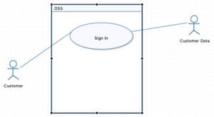

The diagram should now look like this:
Complete the use case diagram
Actors and Use Cases table to complete the use case diagram. Now that you know how to add use case diagram elements, you can use the information from the from the
Completed use case diagrams
When done, Your use case diagram should look like:

Tips
Documentation View
The documentation view provides a mechanism to add documentation to a model element. Although this is useful in many areas of modeling, it is very helpful when doing use case analysis at the beginning of the project where you can use this capability to add textual information to better textually describe the actors and to provide a textual description of the use cases. To show the documentation view and edit its content, right-click on a model element on a diagram and select “Show Documentation view” and the Properties view will display the documentation view.
Adding documentation to a use case
- Right-click on the "FindProducts" use case and select "Show Documentation View" command
- In the "Find Products" input, add your documentation for that use case.
Example of the documentation view.
This is an example of a use case's requirements documented with using user stories.

Adding Structure to models
- Using packages to add structure and layers to a model
- Packages are used to manage groups of similar or related model elements.
- Examples of using packages:
- * Separating common elements into logical groups
- * Separating parts of the model done by separate development teams, making parallel development easier
- :: E.g. elements related an external service such as databases), and layered architectures (e.g., with presentation, business, persistence layers).
- * The use of packages also facilitate traceability across the development lifecycle.
Package Diagram

- Build a simple package diagram for a layered model development approach
Create the package diagram
- Right-click on the model in the model explorer
- Select “New Diagram in the dropdown menu and pick the Light Package Diagram.
- Name the diagram “Packaging exercise” and click “OK”
- The use case diagram has been replaced by the new diagram Package in the model editor, but is still available as a tab. As you create new diagrams, the will be listed there until you close them.
- As well, the palette has changed to display the tools for package diagrams.