Notice: This Wiki is now read only and edits are no longer possible. Please see: https://gitlab.eclipse.org/eclipsefdn/helpdesk/-/wikis/Wiki-shutdown-plan for the plan.
Difference between revisions of "Papyrus-RT/UML-RT/Pass-Through-RelayPorts"
(Created page with "File:PapyrusForRealTime-Logo-Icon.png<br/><br/><br/><br/><span style="font-family: Helvetica,Arial,sans-serif; font-size: 48px;"><b>UML-RT Relay ports a...") |
(Initial page creation) |
||
| Line 3: | Line 3: | ||
__NOTOC__ | __NOTOC__ | ||
| − | + | Understanding pass-through connectors and how they can be implemented in UML-RT (and Papyrus-RT) is the base of interesting modeling patterns. In order to be able to use these correctly, the following explanation has been written. | |
| − | <br/> | + | The following information was taken from [https://bugs.eclipse.org/bugs/show_bug.cgi?id=487356 Papyrus-RT Bug 487356].<br/>The text is from Ernesto Posse based on a discussion with Bran Selic. |
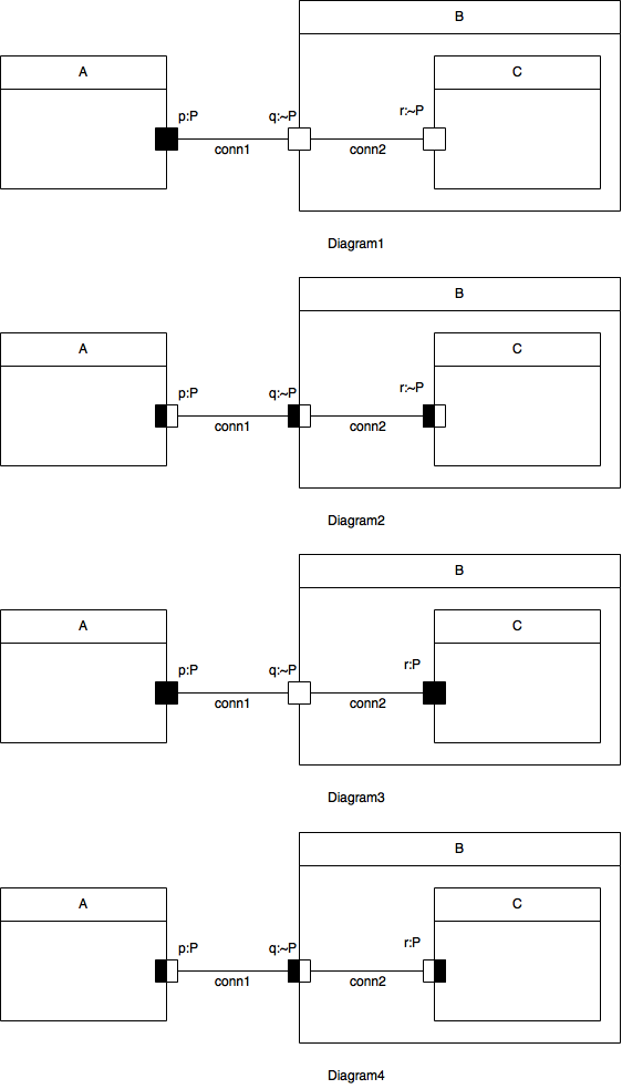
In Figure 1, Diagram 1 shows a legal (delegation) connector (conn2), connecting two ports (q and r) with the same conjugation. Diagram 2 makes the faces explicit. For a base port ( p) the outer face is white and the inner face is black. For a conjugate port (q,r), the outer face is black and the inner face is white. The rule is that a connector can only connect "opposite" faces. Diagram 3 is illegal because, as depicted in Diagram 4, a connector would connect faces with the same colour. | In Figure 1, Diagram 1 shows a legal (delegation) connector (conn2), connecting two ports (q and r) with the same conjugation. Diagram 2 makes the faces explicit. For a base port ( p) the outer face is white and the inner face is black. For a conjugate port (q,r), the outer face is black and the inner face is white. The rule is that a connector can only connect "opposite" faces. Diagram 3 is illegal because, as depicted in Diagram 4, a connector would connect faces with the same colour. | ||
[[File:B487356F1.png|center|top-align|Figure 1]] | [[File:B487356F1.png|center|top-align|Figure 1]] | ||
| − | |||
| − | |||
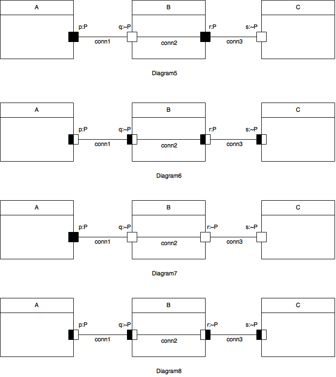
Figure 2 illustrates the case with a "pass-through" connector, where the protocol is *not* symmetric. Diagram 5 is legal, since, as shown in Diagram 6, connectors only connect opposite faces. On the other hand, Diagram 7 is illegal, because, as shown in Diagram 8, conn2 connects faces with the same colour. | Figure 2 illustrates the case with a "pass-through" connector, where the protocol is *not* symmetric. Diagram 5 is legal, since, as shown in Diagram 6, connectors only connect opposite faces. On the other hand, Diagram 7 is illegal, because, as shown in Diagram 8, conn2 connects faces with the same colour. | ||
[[File:B487356F2.png|center|bottom-align|Figure 2]] | [[File:B487356F2.png|center|bottom-align|Figure 2]] | ||
Revision as of 11:55, 16 December 2016
UML-RT Relay ports and pass-through connectors
Understanding pass-through connectors and how they can be implemented in UML-RT (and Papyrus-RT) is the base of interesting modeling patterns. In order to be able to use these correctly, the following explanation has been written.
The following information was taken from Papyrus-RT Bug 487356.
The text is from Ernesto Posse based on a discussion with Bran Selic.
In Figure 1, Diagram 1 shows a legal (delegation) connector (conn2), connecting two ports (q and r) with the same conjugation. Diagram 2 makes the faces explicit. For a base port ( p) the outer face is white and the inner face is black. For a conjugate port (q,r), the outer face is black and the inner face is white. The rule is that a connector can only connect "opposite" faces. Diagram 3 is illegal because, as depicted in Diagram 4, a connector would connect faces with the same colour.
Figure 2 illustrates the case with a "pass-through" connector, where the protocol is *not* symmetric. Diagram 5 is legal, since, as shown in Diagram 6, connectors only connect opposite faces. On the other hand, Diagram 7 is illegal, because, as shown in Diagram 8, conn2 connects faces with the same colour.


