Notice: This Wiki is now read only and edits are no longer possible. Please see: https://gitlab.eclipse.org/eclipsefdn/helpdesk/-/wikis/Wiki-shutdown-plan for the plan.
Sirius/Tutorials/AdvancedTutorial
Contents
- 1 Overview
- 2 Install the basic modeling tool
- 3 Start extending the basic modeling tool
- 4 Going Further
Overview
This tutorial will guide you extending a basic modeling tool with many advanced features of Eclipse Sirius:
- Edition tools: edge creation, edge reconnection, element deletion, label edition
- Graphical improvements: styles customization
- Complexity management: layers, filters, validation rules, quick fixes
- Other kinds of representations: containers, bordered nodes, tables, navigation between representations
- Extensions: Java services
The instructions start from the result of the Sirius Starter Tutorial, a basic modeling tool which simply allows the user to graphically represent men and women of a family and to create new men.
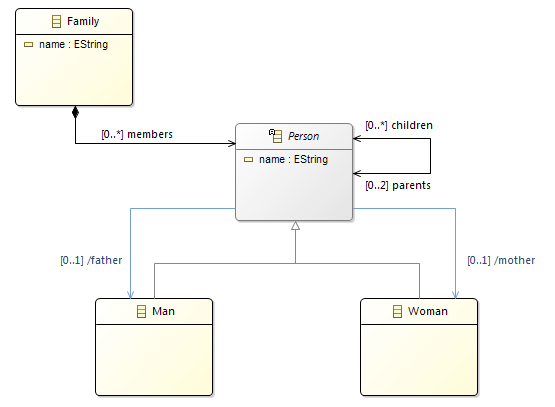
The advanced modeling tool that you will create is based on the same simple Domain Model which describes basic concepts about families.
Note: The screenshots have been created with Obeo Designer 10.0 (based on Sirius 5.0).
Install the basic modeling tool
If you have followed the Starter Tutorial already, you are ready! Directly go to next section: Start extending the basic modeling tool.
Otherwise, start by following the instructions to install the sample Domain Model:
- Import the projects containing the sample Domain Model
- Launch a new runtime from your Eclipse
- Select the Sirius perspective
- Import a sample model
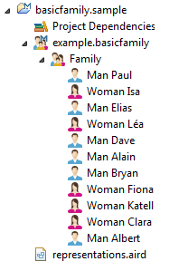
Now, you should have an Eclipse runtime (started from your first Eclipse) with a sample Family model installed in your workspace.
Then, install the solution of the Starter Tutorial. It is implemented by a Viewpoint Specification Project that you need to import into your workspace.
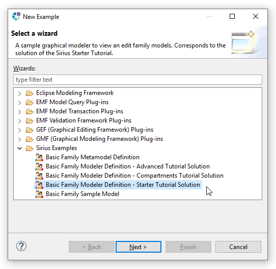
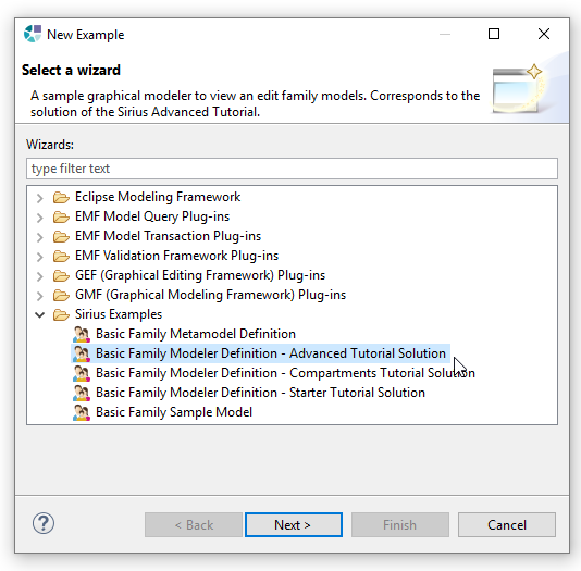
This project can be easily installed from the provided examples (menu File > New > Example... : select Basic Family Modeler Definition - Starter Tutorial Solution).
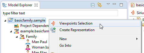
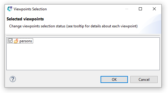
Once the modeler imported in your workspace, activate the persons viewpoint by selecting the menu Viewpoint Selection.
You must activate the persons viewpoint to be able to create the representations which are defined by this viewpoint.
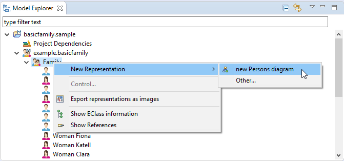
Then right-click on the sample model and select the menu New Representation / new Persons diagram.
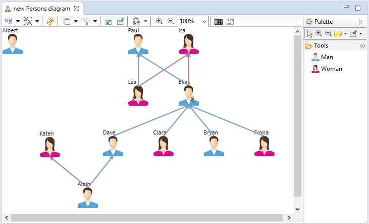
Sirius should create and open a diagram describing the men and women contained in the sample model.
Start extending the basic modeling tool
Note: the solution of the following steps can be installed directly from the samples
Edge Creation Tool
An Edge Creation tool allows the user to create relationships directly from the diagram, by using the palette.
Let's use this tool to allow the user to set the father and the mother relations of a Person.
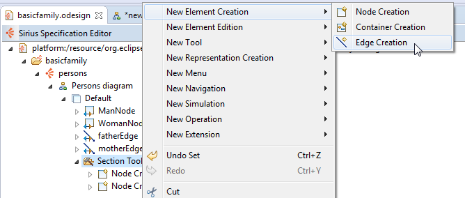
Right click on the Section and select the menu New Element Creation > Edge Creation
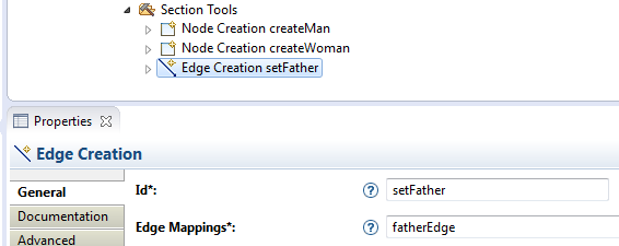
Give an Id to this tool (setFather) and associate it to fatherEdge, the Edge Mapping which defines the father graphical relation.
Set the icon that will appear in the palette (if you don't specify an icon here, Sirius will use a default one):
Then define the operations that will be performed by this tool each time the user will click on it. These operations can use four variables that are automatically set by Sirius:
- source: the first object on which the user has clicked (the source of the relation he is going to create)
- target: the second object on which the user has clicked (the target of the relation he is going to create)
- sourceView: the graphical object representing the source
- targetView: the graphical object representing the target
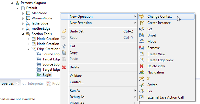
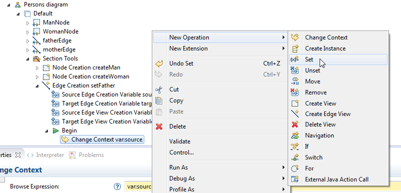
Under the Begin object, create a Change Context.
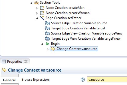
Set its Browse Expression to var:source in order to define the execution context of the next operations.
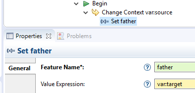
Under the Change Context create a Set.
It will set the father of the first Person clicked (source) to the second Person clicked (target):
- Feature Name:
father - Value Expression:
var:target
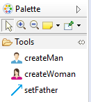
Save the odesign file and you will see a new tool setFather in the palette.
Precondition
To prevent the user to create a father relationship from a person to itself, or to one of its children, you can add the precondition expression aql:preTarget.differs(preSource) and preSource.oclAsType(basicfamily::Person).children->excludes(preTarget) (written in AQL).
This expression uses two new variables:
- preSource: the object on which the user has clicked first
- preTarget: the object under the cursor
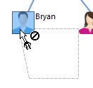
With this precondition, the tool will prevent the creation of forbidden links by showing a specific icon.
Now copy, paste and update the setFather tool to create the setMother tool.
Reconnect Edge Tool
A Reconnect Edge tool allows the user to change the end of a relationship by moving it directly from the diagram.
Let's create a Reconnect Edge tool to change the father and the mother of a Person.
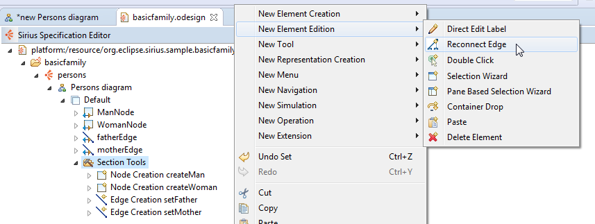
Right click on the Section and select the menu New Element Edition > Reconnect Edge
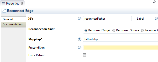
Associate the fatherEdge to this reconnect tool.
This tool comes with six variables:
- source: the object currently attached to the moved end
- target: the object going to be attached to the moved end
- sourceView: the graphical object representing source
- targetView: the graphical object representing target
- element: the object attached to the other end
- elementView: the graphical object representing element
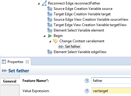
Then create a Change Context and set its expression to var:element (the person who will change his father)
Finally, create a Set to assign the new selected parent (var:target) as father of this person.
Copy, paste and update this tool to create a reconnect tool for mother relationship.
Delete Element Tool
A Delete Element tool specifies which actions have to be performed when the user hits the delete key on an diagram element.
It is necessary on elements which deletion can't be interpreted by Sirius (for example edges) or if you need to perform specific actions.
Let's create a Delete Element tool to specify what to do when the user deletes a paretal relation.
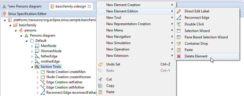
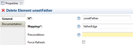
Right click on the Section and select the menu New Element Edition > Delete Element
Associate the fatherEdge to this Delete tool.
When deleting an edge, the variable element refers to the source of the relationship.
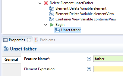
So, create a Change Context and set its expression to var:element (the person which is the children). Then create a Unset on the feature father to remove this relation.
Copy, paste and update this tool to create a delete tool for mother relationship.
Direct Edit Label Tool
A Direct Edit Label specifies how to interpret the modification of graphical object's label in order to modify the model.
Let's create a Direct Edit Label to change the name of a Person directly from the diagram.
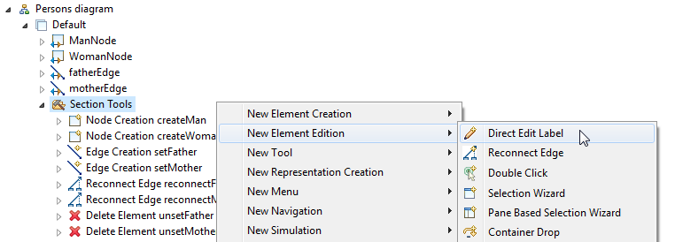
Right click on the Section and select the menu New Element Edition > Direct Edit Label
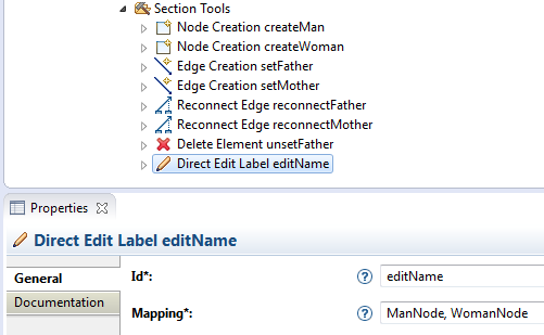
Associate this tool to the objects which have a name: ManNode and WomanNode
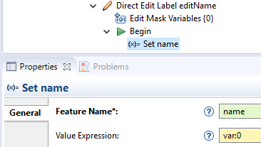
This tool comes with a mask that creates variables depending on the label's value. By default, the mask is set to {0}, which means that the variable named 0 will contain the full value of the label.
Create a Set to indicate the feature of the edited object that will be modified (name) and the value to assign (var:0).
Style Customization
Style Customizations change graphical properties of diagram elements (color, label, size, ...) depending on conditions.
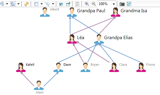
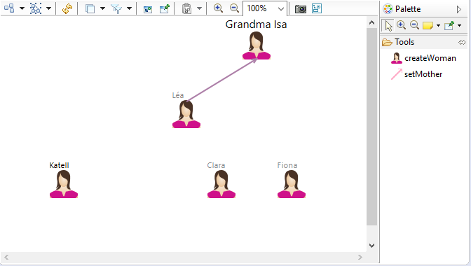
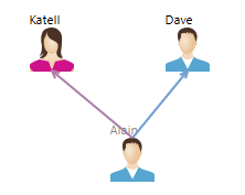
For example, let's change the label of a Person depending on the number of its children:
- Person without children => color label in gray
- Person having more than one children => set label size to 12
- Person having grandchildren => prefix label with Grandpa or Grandma
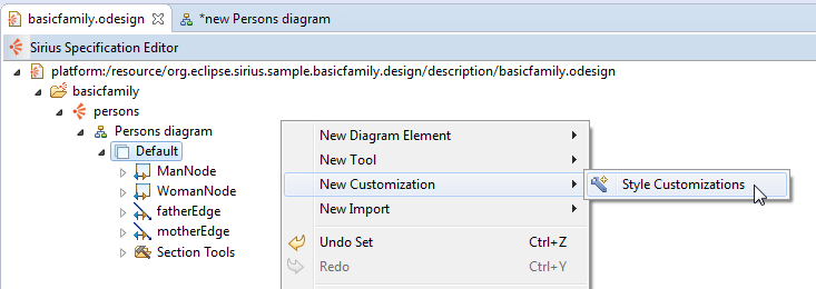
Right click on the Default Layer and select the menu New Customization > Style Customizations. It will group all the different customizations.
Right click on the Style Customizations and select the menu New Customization > Style Customization to create the first customization.
Enter the AQL expression associated to this customization: aql:self.oclAsType(basicfamily::Person).children->size()=0
Then define the graphical properties that will change if the condition is met.
Right click on the Style Customization and select the menu New Customization. To change the label color, create a Property Customization (by selection).
On this Property Customization, select the two Workspace Images for the Applied On field (they hold the label to change), enter labelColor in the Property Name field, then select the gray color.
Note that you can use the automatic-completion to select the applicable property.
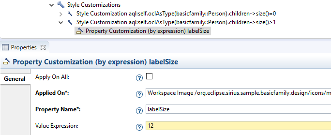
Create a second Style Customizations with the condition: aql:self.oclAsType(basicfamily::Person).children->size()>1
and add a Style Customization (by expression) to set the labelSize to 12.
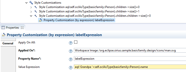
Finally, create a third Style Customizations with the condition: aql:self.oclAsType(basicfamily::Person).children.children->size()>0
Add a Style Customization (by expression) for the Workspace Image corresponding to the Man, enter the property name labelExpression and the expression aql:'Grandpa '+self.oclAsType(basicfamily::Person).name (to prefix the person name with Grandpa).
Do the same with the Woman image and the expression aql:'Grandma '+self.oclAsType(basicfamily::Person).name.
Save the odesign file and see the result on the diagram.
Layers
With Sirius it is possible to allocate specific graphical elements to layers that can be activated/deactivated on demand by the user.
Let's create two layers: one for the Men and one for the Women.
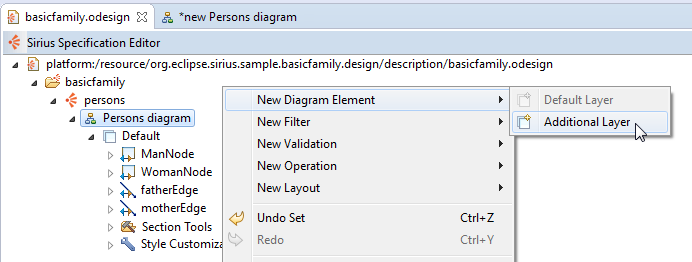
Right click on Persons diagram and select the menu New Diagram Element > Additional Layer.
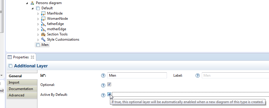
Call this Layer Men and check the option Active by default.
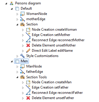
Create a Section in this layer then drag and drop all the elements related to the Man type into this layer.
Create a second Layer Women and drag and drop all the elements related to the Woman type.
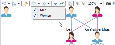
Re-open the sample diagram. You can see the two optional layers Men and Women (selected by default).
If you de-activate the Men layer, only women remain on the diagram. Note that the tools related to men have been hidden too.
Filters
With Filters, Sirius provides an additional mechanism to automatically show or hide elements of a diagram: a condition determines which elements remain visible.
Let's create a Filter to hide persons without children.
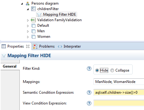
Right click on Persons diagram and select the menu New Filter > Composite Filter.
Set the id to childrenFilter.
Then create a Mapping Filter.
Associate ManNode and WomanNode to this filter and define the Semantic Condition Expression : aql:self.children->size()>0
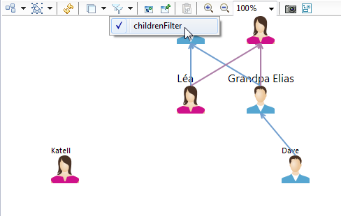
On the diagram, you can now select the filter childrenFilter and see that only persons with children remain visible.
Validation Rules
Validation rules allow the user to evaluate the quality of a model.
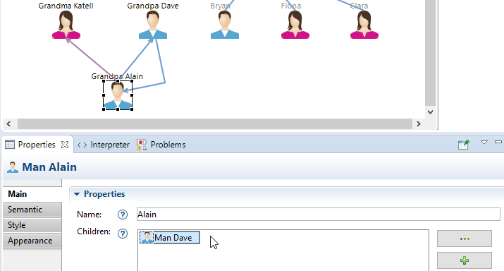
For example, despite the precondition existing on the Eddge Creation tool, users can still create circular parental relations between two persons by using the Properties View:
- select a person with at least one child
- use the Parents widget in the Properties View to add one of the children as a parent
Let's create a Validation Rule to detect this problem.
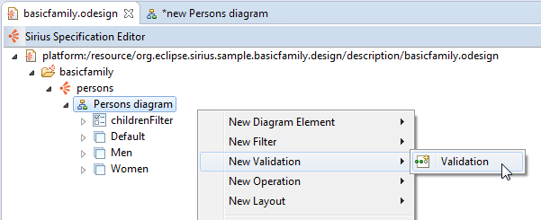
Right click on Persons diagram and select the menu New Validation > Validation.
Set the name FamilyValidation to this Validation. Then create a Semantic Validation Rule.
Set the properties of this rule:
- Level:
Error - Target Class:
basicfamily::Person - Message:
aql:self.oclAsType(basicfamily::Person).father.name+' should not be both the child and the father of '+self.oclAsType(basicfamily::Person).name
Then create an Audit (a condition corresponding to this rule) with the expression aql:self.children->excludes(self.father).
To test this rule, introduce an error in the model with the Property View: add the father of a person into the list of his children.
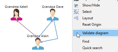
Then right-click on the diagram and select the menu Validate diagram.
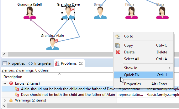
The circular father relationship is detected and a decorator (corresponding to the rule level) is displayed on the persons with this problem. A tootip contains the error message.
Quick Fixes
Fixes can be provided to the user for solving the problem automatically.
For example, we can propose to unset one of the two father relations.
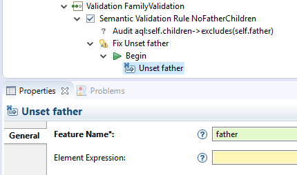
Right-click on the Rule and select the menu New > Fix.
Set the name Unset father to this Fix and create a Begin. Then create a Unset and enter father in the Feature name.
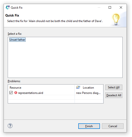
If you open the Problems View, you can right-click on one of the errors and select the menu Quick Fix.
A dialog opens which proposes the available fixes.
Select Unset father and click on Finish: the father of the selected person is automatically unset and the problem is solved.
Object-Centered Diagram
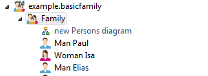
The Persons diagram is a representation related to the whole model: it displays all the members of the family. This is the reason why it belongs to the Family instance, as you can see in the Model Explorer.
With Sirius, you can create a representation on any instance of the model. For example, let's create a person-centered diagram to show only the relationships of a given person.
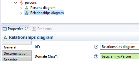
Right-click on the persons viewpoint and select the menu New Representation > Diagram Description.
Associate the basicfamily metamodel to this diagram (see Starter Tutorial) then set these properties:
- Id:
Relationships diagram - Domain Class:
basicfamily::Person
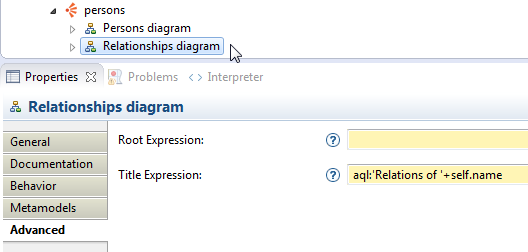
In the Advanced tab, set the Title Expression to aql:'Relations of '+self.name in order to customize the name of the diagram with the person's name.
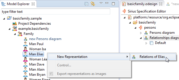
Save the odesign file. Now, you can right click on a person in the Model Explorer and create a new representation of type Relationships diagram.
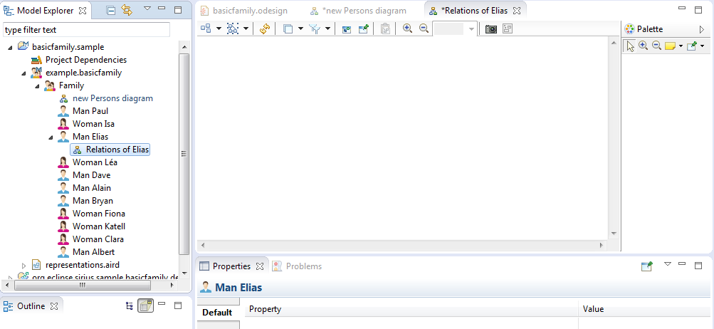
The result is a blank diagram, since we have not yet specified its content.
Container
A Container is a kind of diagram element that can contain other diagram elements.
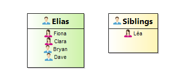
On the Relationships diagram, let's use two containers to represent:
- The current person (who owns the diagram) with:
- each children in a list
- its parents as border nodes
- The siblings of the current person:
- each sibling in a list
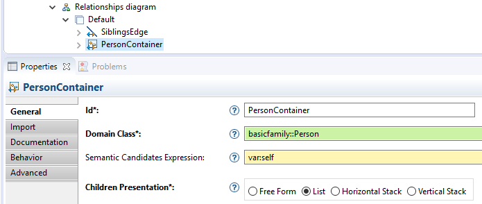
Right-click on the Layer and select the menu New Diagram Element > Container.
For this first container, set these properties:
- Id:
PersonContainer - Domain Class:
basicfamily::Person - Semantic Candidate Expression:
var:self(the current person) - Children Presentation:
List
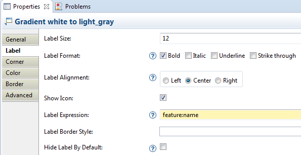
To define the graphical rendering of this container, right-click on it and select the menu New Style > Gradient.
On this style, set these properties:
- Label Tab:
- Label Size:
12 - Label Format:
bold
- Label Size:
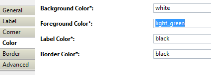
- Color Tab:
- Foreground Color:
light_green
- Foreground Color:
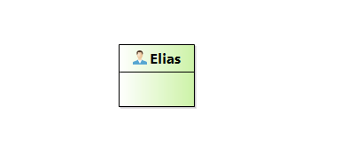
Save the odesign file and you see a green container appear on the diagram that you have created for a person.
Sub Nodes
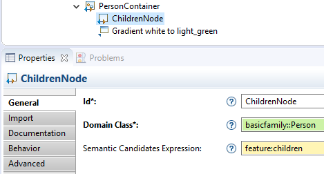
Now, to display children inside this container, right-click on the container definition and click on the menu New Diagram Element > Sub Node.
On the Sub Node set these properties:
- Id:
ChildrenNode - Domain Class:
basicfamily::Person - Semantic Candidate Expression:
feature:children
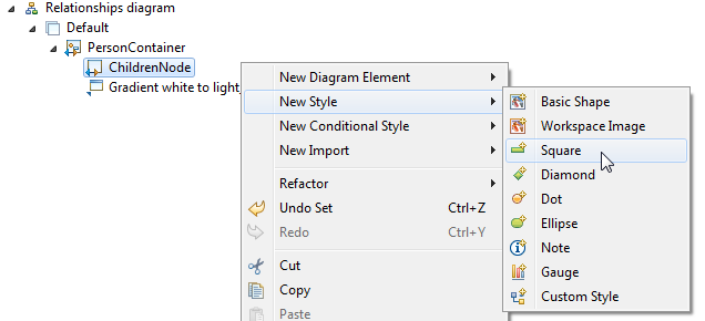
Then create a style. Note that the kind of style is not important here: for elements in a list, the style is used only to specify the label.
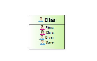
Save the odesign file, and now you can see the children listed inside the container.
Copy paste PersonContainer to create another container for siblings.
Change these properties on this new container description:
- Container > Name:
SiblingContainer - Gradient > Label Size:
10 - Gradient > Label Expression:
Siblings - Gradient > Foreground Color:
light_yellow
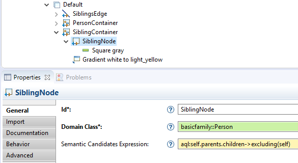
And these properties on the Sub Node:
- Id:
Sibling Node - Semantic Candidates Expression:
aql:self.parents.children->excluding(self)
Save the odesign file, and now you can see the siblings listed inside a second container.
Border Node
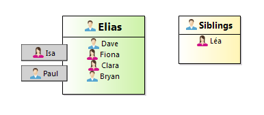
Now let's add Border Nodes to the first container to display the parents of the current person.
Right-click on PersonContainer and select the menu New Diagram Element > Border Node:
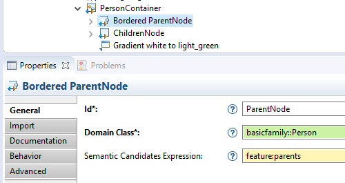
Set these properties to the border node:
- Id:
ParentNode - Domain Class:
basicfamily::Person - Semantic Candidate Expression:
feature:parents
Add a square as style with a White color.
Save the odesign file and now, after manual resizing, you should see the parents attached on the border of the first container :
Edge between containers
Like nodes, Containers can be linked with Edges.
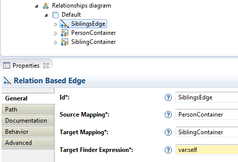
Right-click on the Default layer and select the menu New Diagram Element > Relation Based Edge.
Set these properties to the edge:
- Id:
SiblingsEdge - Source Mapping:
PersonContainer - Target Mapping:
SiblingsContainer - Target Finder Expression:
var:self(the second container represents the current person also)
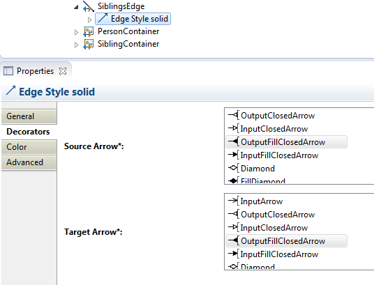
On the style of the edge (automatically created), you can specify the end's decorators.
Save the odesign file, and now you can see a link between the two containers.
Double-click
Now we can create a specific diagram for each person. To facilitate the navigation between all these diagrams, let's create a Double Click tool that allows the user to navigate from any person on a diagram to its dedicated diagram.
Go back to the first diagram, right click on the Section in the first Layer and select the menu New Element Edition > Double Click.
On the Mappings property of the Double Click select all the elements of the modeling tool that represent a Person (except the two containers, since it doesn't make sense to navigate to the current diagram).
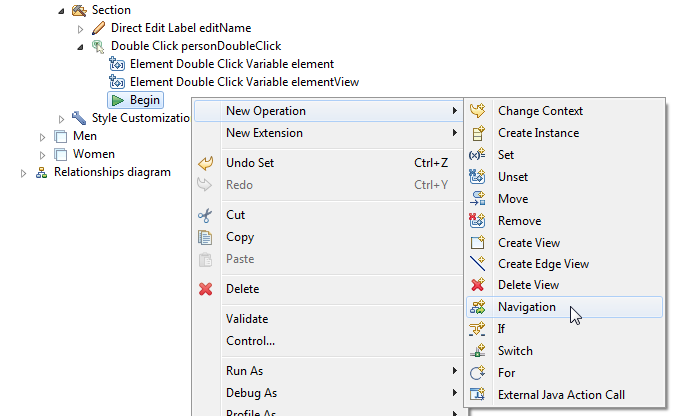
To specify the action of the Double Click, right-click on the Begin and select the menu New Operation > Navigation.
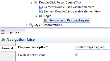
Then set these properties to the Navigation :
- Diagram Description:
Relationships diagram - Create if not Existent:
true
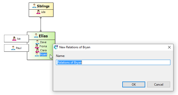
Save the odesign file, close and reopen your diagrams. Now you can double-click on persons to open their corresponding Relationships diagram. If this diagram has not been created yet, Sirius will propose to create it.
Table
With Sirius it is also possible to represent model elements with a Table.
Let's create a table that lists all the persons, with this information for each:
- father's name
- mother's name
- number of children
Right-click on the Viewpoint and select the menu New representation > Edition Table Description.
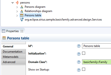
Set the basicfamily metamodel to this table (see Starter Tutorial) then set these properties:
- Id:
Persons table - Domain Class:
basicfamily::Family
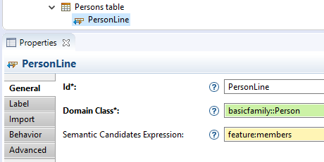
In this table, you need lines to represent the persons. So, right-click on the Table and select the menu New Table Element > Line.
Set these properties to the line:
- Id:
PersonLine - Domain Class:
basicfamily::Person - Semantic Candidates Expression:
feature:members - Header Label Expression (Label tab):
feature:name
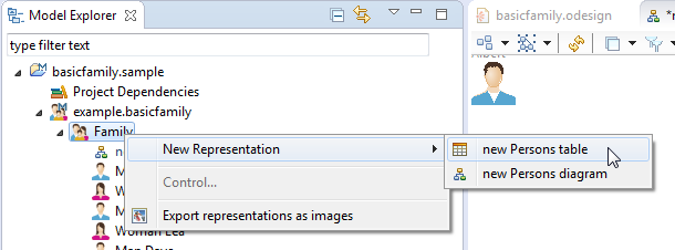
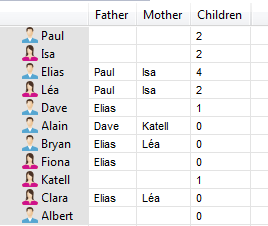
Save the odesign file then right-click on the Family instance in the Model Browser and click on the menu New Representation. You can see a new menu new Persons table.
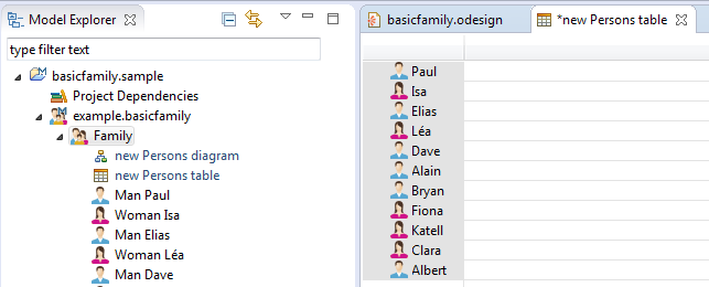
If you select this menu, Sirius creates and opens a table with all the family's members.
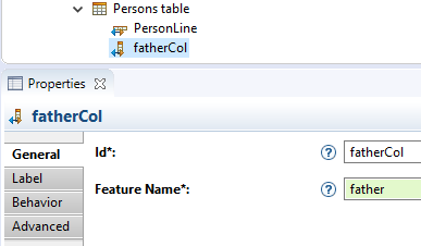
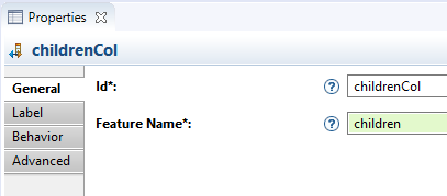
Now, let's add columns to this table to display more information for each person. So, right-click on the Table and select the menu New Table Element > Feature Column.
Set these properties to the column:
- Id:
fatherCol - Feature Name:
father
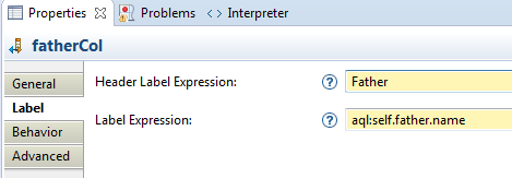
Select the Label tab and set these properties:
- Header Label Expression:
Father - Label Expression:
aql:self.father.name
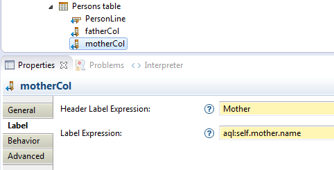
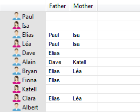
Copy and paste fatherCol then rename father by mother in all the properties.
Save the odesign file and see the two new columns.
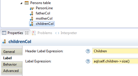
Finally, add a new Feature Column to display the number of children.
Set these properties to the column:
- Id:
childrenCol - Feature Name:
children
Select the Label tab and set these properties:
- Header Label Expression:
Children - label Expression:
aql:self.children->size()
Save the odesign file and see the third column.
Java Services
When expressions become complex, you should write Java Services instead.
For example, let's create a Java Service to compute the number of cousins and display this information in the table.
Add a method named getCousinsNumber in the Java class Services.java (in src/org.eclipse.sirius.sample.basicfamily.design).
package org.eclipse.sirius.sample.basicfamily.design;

import java.util.ArrayList;
import java.util.List;

import org.eclipse.sirius.sample.basicfamily.Person;

/**
 * The services class used by VSM.
 */
public class Services {

	public int getCousinsNumber(Person person) {
		List<Person> cousins=new ArrayList<Person>();
		List<Person> parents=person.getParents();

		for (Person parent: parents) {
			for (Person grandParent: parent.getParents()) {
				for (Person uncleOrAunt: grandParent.getChildren()) {
					if (!parents.contains(uncleOrAunt)) {
						for (Person cousin:uncleOrAunt.getChildren()) {
							if (!cousins.contains(cousin))
								cousins.add(cousin);
						}
					}
				}
			}
		}
		return cousins.size();
	}

}
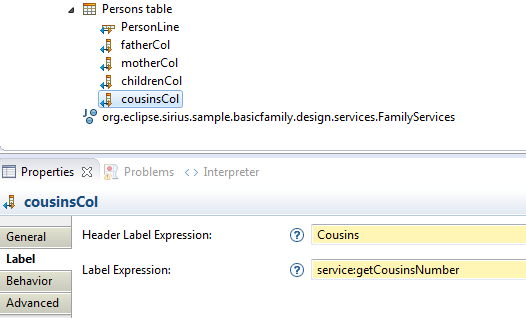
To use the service getCousinsNumber in the table, create a new Feature Column named cousinsCol and invoke the service in the expression (service:getCousinsNumber).
Note: The Feature Name property can be set with any valid feature name (name, parents, ...), since the label will be computed independently (just based on the current person).
Note: Since Sirius 6.0, you can select a service from an expression field, then hit F3 to open the source code of this service.
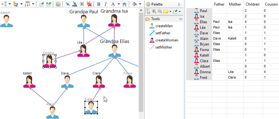
In the table, now you can see a new column Cousins containing the number of cousins for each person (zero in the sample model). Use the diagram creation tools for creating more persons such as some of them have cousins: Sirius will automatically update the number of cousins in the table.
Going Further
This advanced tutorial is now finished, congratulations! If you wish to go further and explore other Sirius features, you can continue with the Compartments Tutorial which explains how to create compartments within a container.

