Notice: This Wiki is now read only and edits are no longer possible. Please see: https://gitlab.eclipse.org/eclipsefdn/helpdesk/-/wikis/Wiki-shutdown-plan for the plan.
Papyrus-RT/User/User Guide/Getting Started/v0.7-8
Getting Started with Papyrus for RealTime v0.7/0.8
Contents
- 1 Introduction
- 2 Create a Papyrus for Real Time Project containing a UML-RT model.
- 3 Add profiles the model
- 4 Add UML-RT Runtime Services Library
- 5 Create a protocol to specify the messages that can be exchanged between players
- 6 Defining the Tutorial's "PingPong" System's Structure
- 7 Create the Pinger Capsule
- 7.1 Create the Pinger capsule
- 7.2 Open Pinger's Composite Structure Diagram
- 7.3 Add a port to Pinger and set its type
- 7.4 Rename the port
- 7.5 Add IO libraries
- 7.6 Create Pinger's state machine
- 7.7 Set the state machine's stereotype and properties
- 7.8 Create the state machine's content
- 7.9 Add "onPong:" transition trigger to the state machine
- 7.10 Add an effect to the "onPong" transition to log it was taken.
- 7.11 Add the "Playing" entry action behavior to the state machine
- 8 Create the Ponger Capsule
- 8.1 Create the Ponger capsule
- 8.2 Open Ponger's Composite Structure Diagram
- 8.3 Add a port to Ponger and set its type
- 8.4 Rename the port and set its conjugation
- 8.5 Add IO libraries
- 8.6 Create Ponger's state machine
- 8.7 Set the state machine's stereotype and properties
- 8.8 Create the state machine's content
- 8.9 Add "onPing:" transition trigger to the state machine
- 8.10 Add an effect to the "onPing" transition to log it was taken.
- 9 Implement the System as the Top Capsule
- 10 Execute the model
- 11 Congratulations!
Introduction
This tutorial will show the creation of a simple model using Papyrus for RealTime version 0.7.0 (and 0.8, based on Eclipse Mars).
As a precondition to going through this tutorial, you must have Papyrus for Real Time installed and the tool open. Please see Installing Papyrus-RT for the various methods to install Papyrus for Real Time.
Note: The instructions in this tutorial are illustrated using Linux. Steps and images may differ slightly if the installation is done on a different operating system (both Windows and Mac OS are supported for developing models). Some of these differences have been indicated when known, but some may also be missing.
At its base, a UML-RT model consists of capsules (UML active classes with composite structure) that communicate through ports defined by protocols (collaboration specifications) These protocols specify the messages (signals) that can be exchanged between capsules, as well as their payloads. Hierarchical state machines are used to represent the behavior of capsules, where transitions between states are triggered by messages received on the capsule's ports.
If you are not familiar with UML-RT and want to know a bit more, you should take a look at the Papyrus Overview page.
The model that will be created as part of this tutorial is a simple, "PingPong" game with two players. In this model, implemented using UML-RT, two players will be playing an eternal game of ping pong.
It is a very simple model that will show how a UML-RT model is constructed. Each player will be portrayed using UML-RT capsules and a UML-RT protocol will be used to define how the ball is exchanged between players through ports on each player capsule.
Create a Papyrus for Real Time Project containing a UML-RT model.
Papyrus for Real Time is a Domain-Specific Modeling Language (DSML) tool based on Papyrus. We will use the Papyrus Project creation wizard to create a project configured for Papyrus for Real Time.
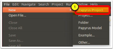
Select File -> New -> Papyrus Project
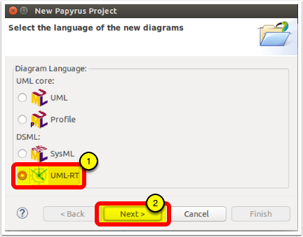
Selecting the language to be used for the model
In the resulting dialog:
- Select UML-RT as the language for the model that will be created by clicking on the radio button next to the UML-RT icon
- Click on [Next].
Define the project
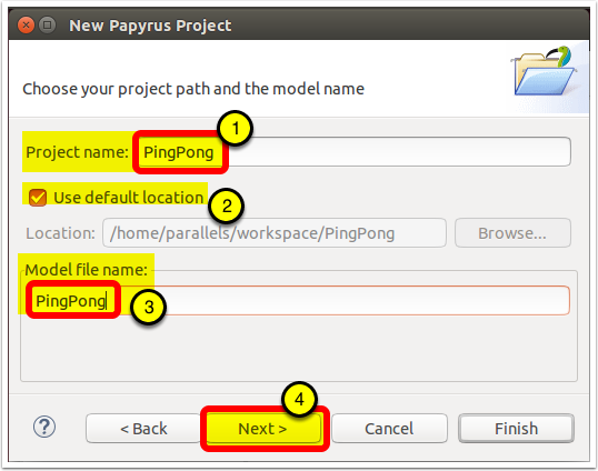
You can now define the project's name and its location, as well as the name of the model file that will be created.
- Enter the name for the project. This project can hold multiple artefacts and will contain a Papyrus model by default. For this tutorial, we will use the name "PingPong".
- By default, the project will be created in the current workspace. You can, however, select an alternative location if, for example, you wish to store your project under source control.
- Enter "PingPong" as the model file name.
- Click on [Next]
Provide model initialization information
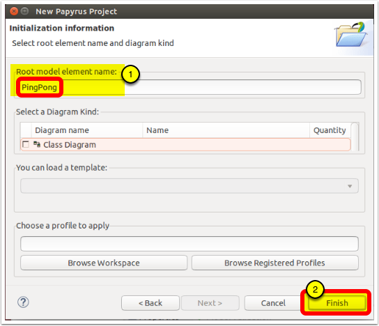
There is more information that can be provided to create a useful model.
- The "Root model element" is a representation of the model itself. For this tutorial, and for consistency, we will name it "PingPong".
- There is no more information to add on this dialog as they are already set in the wizard. Click [Finish] to create the project and contained model.
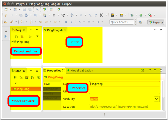
As shown in the image below, you should now have a project named "PingPong" containing a "PingPong" model in the Project Explorer as well as that model opened in the Model Explorer.
Project and Model Created
After expanding the "PingPong" project in the Project Explorer and the "PingPong" model in the Model Explorer, you will see that they have both been created and are now available for modeling.
Add profiles the model
A lot has been done already to create an empty model and you have seen, in the previous step, that the base UML-RT profile has been applied. There are a few more components that need to be added to enhance the experience and the capabilities of the tool.
The first step will be to add some profiles.
Select the PingPong model in the Model Explorer and, in the Properties View, select the "Profile" tab.
We will start by adding two profiles to the model:
- "UML RT StateMachines" defines stereotypes and rules for state machines to support UML-RT specific semantics;
- "UML-RT C++ Property Set Profile" defines stereotypes that enable more precise code generation for many model elements.
Both these profiles are part of the Papyrus-RT distribution and have already been registered during installation.
- With the "PingPong" model selected in the Model Explorer, click on the "Profile" tab of the Properties view.
- Click on the "Apply registered profile" button
Select the profiles to be added to the model
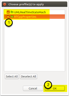
- In the resulting dialog, select the both the "UML RT StateMachines" and "UML-RT C++ Property Set Profile" entries.
- Click [OK]
Add profiles to the model
- In the resulting dialog, click "Select All"
- Note that both profiles are checked
- Click [OK]
The new profiles are now applied.
Add UML-RT Runtime Services Library
A model library containing elements and protocols from the UML-RT Runtime Services layer is also available. This library contains class definitions and protocols that are useful, and in some cases, essential, for the creation of UML-RT models.
This library needs to be imported before it can be used.
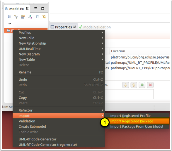
Open the package import dialog
- Right-click on the model in the Model Explorer and select "Import > Import Registered Package"
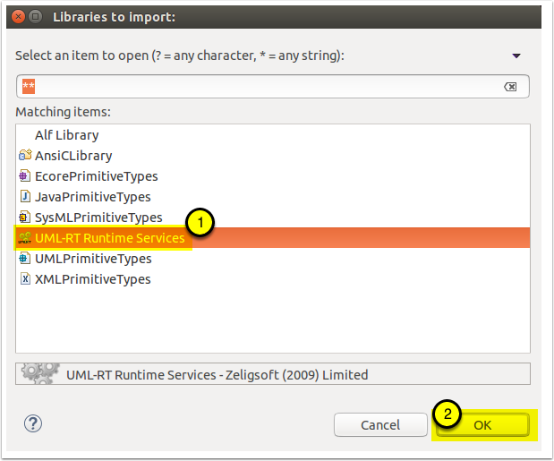
Import the "UML-RT Runtime Services" package
- In the resulting dialog, select the "UML-RT Runtime Services" package from the list
- Click [OK]
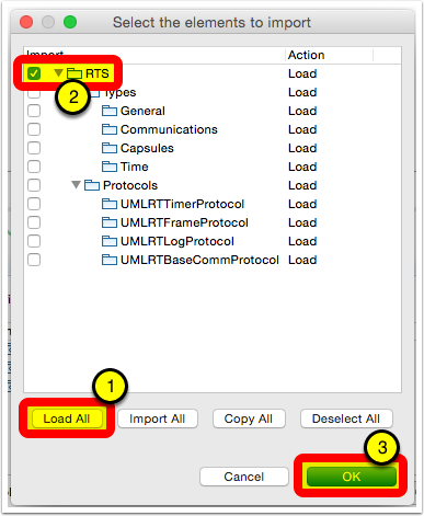
Import all parts for the UML-RT model library
- Click on [Load All]
- Note that only the top-level element is selected - that is the expected behavior as it contains everything.
- Click on [OK]
Repeat the previous steps and select "UMLPrimitiveTypes" as the library to import.
The "UMLPrimitiveTypes" library contains the standard UML types. These can be used to specify property types. To use more specific or specialized base types, you could also use the "AnsiCLibrary" or the properties defined as part of the "RTCppProperties" stereotype. In this tutorial, we will not have a need to use specific types.
The model libraries are now available to the model developer
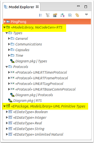
You can now see that both the "RTS" and "UML Primitive Types" libraries are imported into the model.
Note 1: Neither of these model libraries are stored within the "PingPong" model. They are actually part of Papyrus-RT plugins and are "read-only". You can, however, still make use of their content as part of the modelling of "PingPong".
Note 2: The code generator handles the "RTS" library is a special way and will not generate code for it as it only reflects the actual runtime services, which are provided separately as part of the Papyrus-RT distribution.
We are now ready to start our modelling our PingPong system.
Create a protocol to specify the messages that can be exchanged between players
Let's start by determining how the PingPong ball will go from one player to the other. To do this, we can think of the ping pong ball as a message to the other player to which they need to reply (hit the ball back). In UML-RT, the structure that governs the messages that can be exchanged between entities (players in this case) is a protocol.
Protocols define protocol messages that define how messages can be sent and received between model elements (called "Capsules" in UML-RT - more on that later). These protocol messages can be incoming, outgoing, or symmetrical (i.e., both ingoing and outgoing).
In the case of protocols that are not purely symmetric, i.e., that have either or both incoming and outgoing messages, there is also a need for the concept of conjugation, i.e., of reversing the role of the protocol, a concept that will be addressed further when used later in this tutorial.
In the case of this Getting Started tutorial, we could create a symmetric protocol where there would be a single symmetrical protocol message called, for example, "ball". However, to better explore the concept of protocols, we will define our "PingPong" protocol to have one outgoing protocol message called "ping" and one incoming protocol message called "pong".
Create the protocol
The first step is to create the protocol itself.
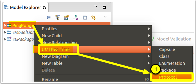
- Right-click on the "PingPong" model in the Model Explorer and select "UMLRealTime > Protocol"
You now have a "protocol" in the Model Explorer.
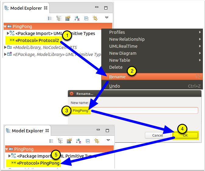
Rename the protocol
Give the protocol a better name.
- Right-click on the protocol in the Model Explorer
- Select "Rename"
- In the dialog, provide "PingPong" as the new name
- Click [OK]
- The protocol has been renamed
Add protocol messages to the protocol
A protocol is actually a complex construct and, as part of the UML-RT DSML, we are hiding its complexity so you do not need to know what lies beneath to create models!
Our protocol will "ping" its opponent and, in return, will respond to a "pong". This tells us that there will be a "ping" outgoing protocol message and a "pong" incoming protocol message.
Tip: Protocols should be defined from the client's perspective. In practice, this means that the provider of the service defined by the protocol will have their ports conjugated and the client's ports will by un-conjugated. This makes sense as there will typically be more clients than service providers, so adopting this best practice will reduce the number of ports that need to be conjugated.
In the case of this model, it does not matter as there is no distinct service provider or client. After all, in a game of ping pong, both sides "serve"! In this tutorial, we will define the protocol from the point fo the player that will "ping".
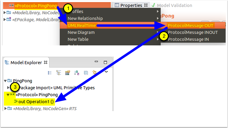
- Right-click on the protocol
- Select to create a "UMLRealTime > ProtocolMessage Out".
- Expand the protocol (by clicking on the right-pointing triangle at its left) and notice that a new protocol message is available.
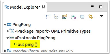
Rename the outgoing protocol message
Right-click on the new protocol message, select "Rename", and change its name to "ping".
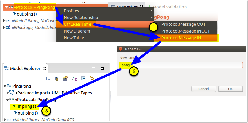
Add a "pong" Incoming Protocol Message
To create the "pong" message, use the same process as for the creation of the "ping" protocol message, above, opting to create a "ProtocolMessageIn" instead and renaming the protocol message "pong"
- Right-click on the PingPong protocol and select "UMLRealTime > ProtocolMessageIn"
- Rename the resulting protocol message to "pong"
- You now have a "pong" protocol message in addition to "ping".
The "PingPong" protocol is now complete
The protocol and its protocol messages can now be seen in both the Model Explorer and the Properties view.
Defining the Tutorial's "PingPong" System's Structure
We will need to create three capsules for this tutorial model:
- Two capsules representing the two players ("Pinger" and "Ponger")
- We will be creating two capsules to highlight some aspects of the communication mechanisms, especially related to how ports are used with asymmetric protocols. If we had a symmetric protocol, we could simply use two instances of the same capsule, and that would be a less interesting model for a tutorial.
- A top capsule representing the complete system ("Top")
- In UML-RT, the building blocks are capsules and there is always a top capsule that represents the system to be built. The complete set of capsules that are required to implement the system's functionality are then included by the containment hierarchy from this top capsule.
Create the Pinger Capsule
Let's start by creating the "Pinger" capsule
Create the Pinger capsule
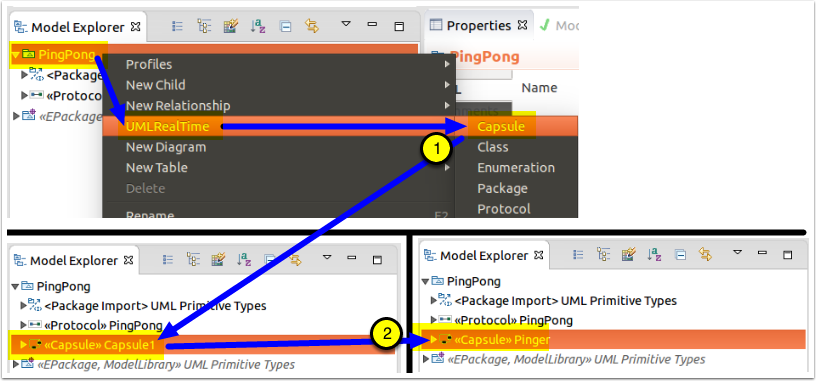
- Right-click on the PingPong model in the Model Explorer and select "UMLRealTime > Capsule"
- Rick-click on the newly created capsule and select "Rename" to change its name to "Pinger"
Open Pinger's Composite Structure Diagram
Because of the importance of capsule containment in UML-RT, and for the convenience of the user, a composite structure diagram is automatically created for each capsule.
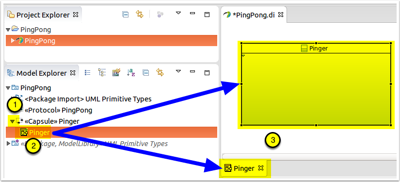
- Click on the right-facing triangle to the left of the "Pinger" capsule to show its contents
- The element displayed is Pinger's composite structure diagram. Double-click on it
- The diagram is now shown in the editor view
- A tab at the bottom indicating the diagram name. Tabs at the bottom of the editor view allow you to easily switch between open diagrams
Add a port to Pinger and set its type
Pinger still needs to communicate with Ponger when it hits the ball. To do this, it needs a port that implements the protocol that we defined earlier.
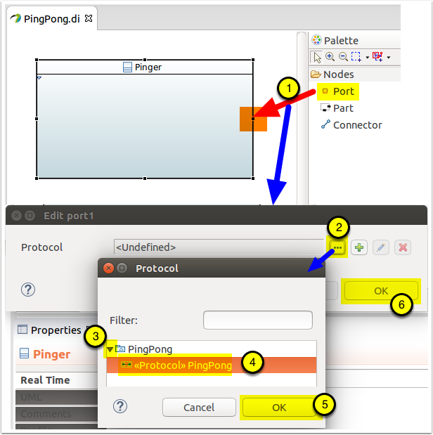
- In the editor pane, select the Port entry in the "Nodes" section of the Palette, click on the right border of "Pinger" (on the diagram)
- In the resulting dialog, click on [...] to select the protocol
- Expand "PingPong"
- Select "«Protocol» PingPong"
- Click [OK]
- Click [OK]
Rename the port
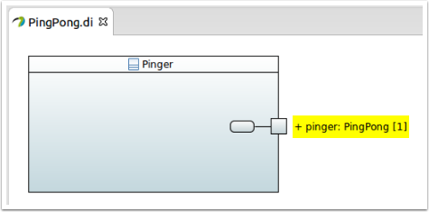
By default, the port will be created with the name in edit mode. At this point, you can just type in its name:
There are three other ways to rename the port:
- Double-click on the port label and enter the new name
- Right click on the port in the Model Explorer, select "Rename", and enter the new name
- Select the "Name" property in the Properties view and enter the new name
Note: ports are properties of the capsule and are typically named with a leading lowercase character.
Add IO libraries
In order to see the execution of the model, once generated and built, we will need to print something to the screen, i.e., to "stdout". In order to do so, we will need to specify the header files that need to be included to give the capsule access to these C++ functions.
This is accomplished though stereotype properties that are used by the code generator to create the correct includes in the generated code.
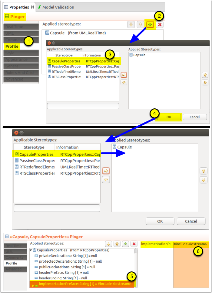
- Make sure that the "Pinger" capsule is selected and its Properties displayed with its "Profile" tab selected.
- Click on the [+], right of "Applied Stereotypes"
- In the resulting dialog, double-lclick on the "CapsuleProperties" entry in the "Applicable Stereotypes" box to move it to the "Applied Stereotypes" and click [OK] to apply the stereotype. This stereotype allows the modeler to set C++ specific constructs to help in the development of the executable model.
- Expand the "CapsuleProperties: stereotype to see its properties and select the "implementationPreface" property.
- In the "Implementation box, type in the following: #include <iostream>
That's all we need for now, we will see how to use this import during the creation of the the capsule's behavior.
Create Pinger's state machine
In UML-RT, all behavior is modeled using hierarchical state machines.
These state machines are dubbed "reactive" because actions (or chains of actions) can only be taken as a result of a message being received on the capsule's ports - so they always react to a message. Reception of a message typically results in one of the state machine's transitions being taken. Each transition exiting from a state has a trigger defined by a port and signal (i.e., protocol message for that port), determining when they can be taken (triggered). Fine-grained actions, typically as opaque expressions, can be provided for transitions, as well as for states' entry and exit.
Pseudostates can also be used to implement logic (choice points), continuation (junction, state entry and exit points - limited to a single outgoing transition), and history (deep and shallow).
Each state machine has an initial pseudostate that is triggered when the state machine if first instantiated, providing initialization capability.
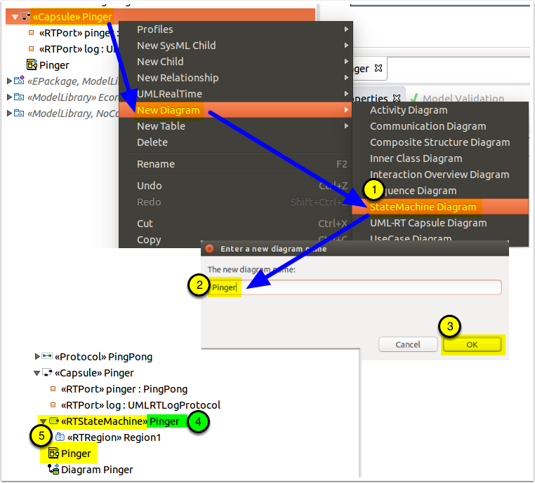
- Right-click on "Pinger" in the Model Explorer and select "New Diagram > StateMachine Diagram"
- In the resulting dialog, name the state machine diagram "Pinger"
- Click [OK]
- [Optional] Rename the state machine to "Pinger"
- Both the state machine and its diagram are now available
Set the state machine's stereotype and properties
Note: The tooling does not yet set all the properties for a UML-RT state machine, so you will have to set them manually.
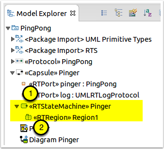
- Keeping the "Pinger" state machine selected in the Model Explorer, use the Profile tab of the Properties Explorer to add the "RTStateMachine" stereotype to the state machine.
- Expand the "Pinger" state machine in the Model Explorer to show and select the contained "Region1" region and then add the "RTRegion" stereotype to it.
1.
Create the state machine's content
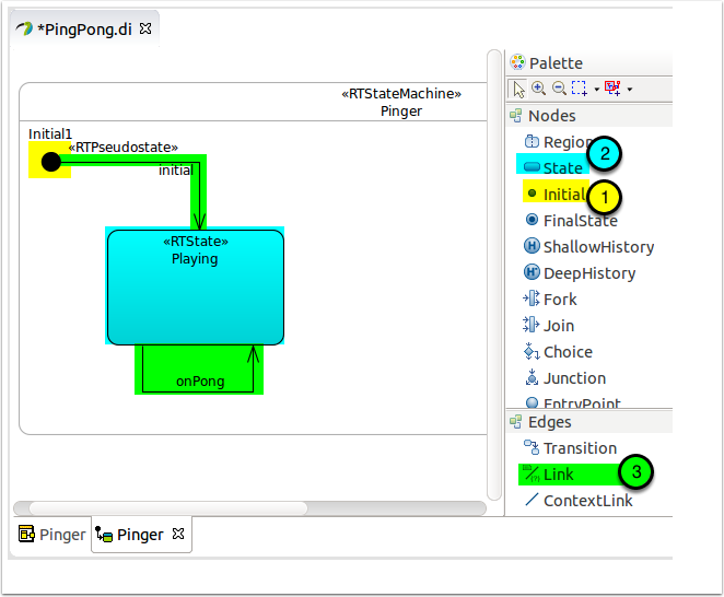
The state machine for Pinger is rather simple. It consists of a single state "Playing" with a self-transition triggered on receiving the "pong" message on the "pingPort".
However, we will also want "Pinger" to start the match, so we will need to do so during or right after the initialisation of the capsule. We can do this because capsule behavior only starts after all static capsule parts are created, so the message queues are already in place to receive messages. Because we do not want to have to issue the same code twice, and since "Pinger" will send a ball each time it receives a pong message, we will use a junction point to be able to reuse a transition's code.
- Using the Palette's "Nodes" drawer, add an "Initial" pseudostate to the top left of the capsule's state machine and apply the "RTPseudostate" stereotype to it. You can leave its name as is or change it as you please.
- Using the Palette's "Nodes" drawer, add a "State" below and to the right of the "Initial" pseudostate, name it "Playing", and apply the "RTState" stereotype to it.
- Using the Palette's "Edges" drawer, draw a "Transition" from "Initial" to "Playing" named "initial", and another from "Playing" to itself named "onPong". Note 1: The start and end are very important when drawing a transition and it defines the direction, the first click being the origin and the second the destination. Note 2: It is a good idea to name transitions as this helps in understanding the diagram and, also, in debugging later on - here, we have used a short form of the trigger event. Note 3: Setting the transition to be "rectilinear" is useful when drawing state machines: right-click on a transition and select "Format > Line Style > Rectilinear Style Routing.
Add "onPong:" transition trigger to the state machine
As indicated previously, the "Initial" transition does not need a trigger as it is taken automatically when the state machine is first instantiated. However, for the "onPong" transition to be taken, we will need to define a trigger for the transition that will determine when the transition can be taken.
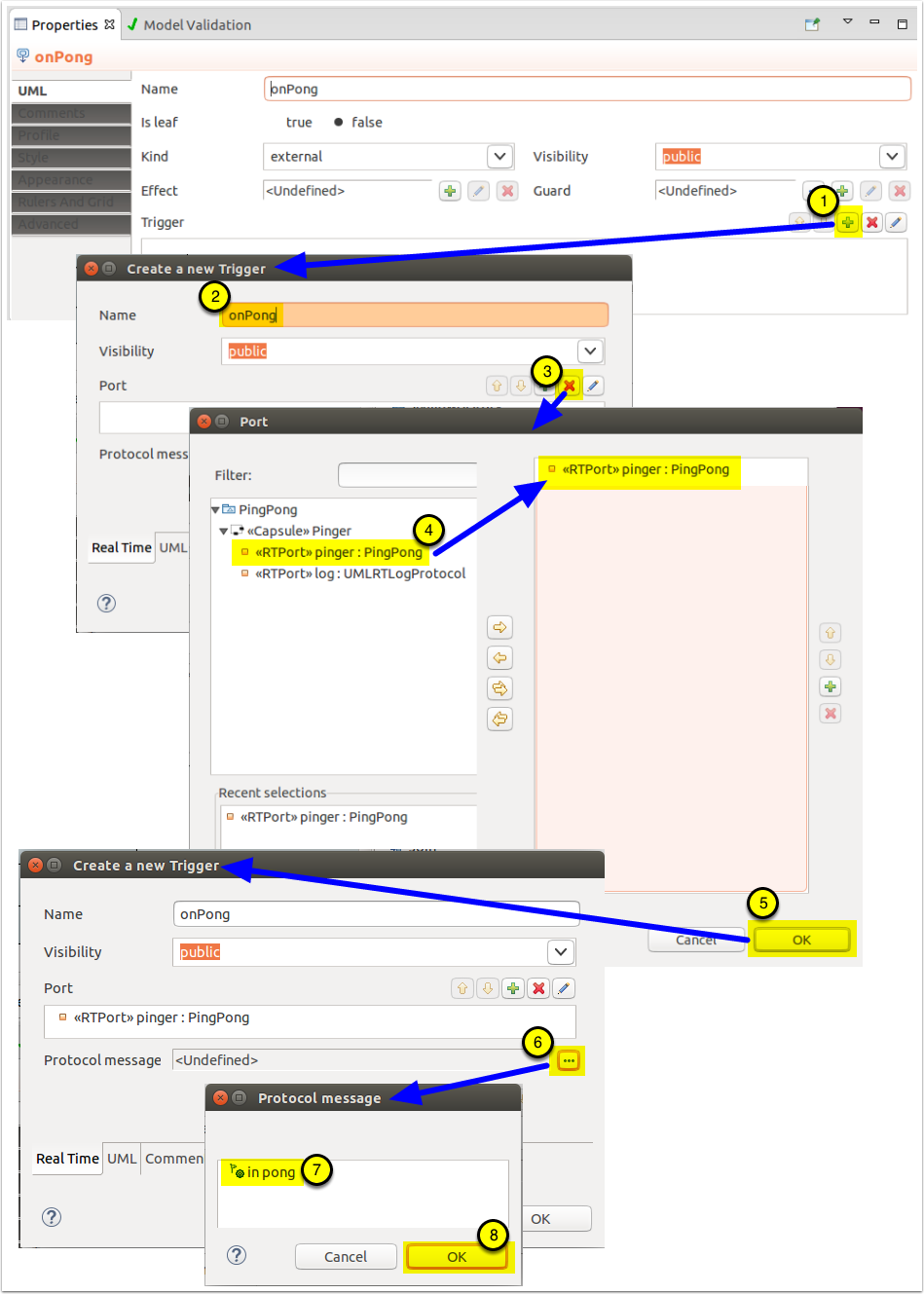
- Select the "onPong" transition. In the Properties view's UML Tab, click on the [+] to the right of the "Trigger" field to create a new Trigger.
- In the resulting "Create a new Trigger" dialog, set the name to "onPong".
- Click on the [+] to the right of the "Port"
- On the resulting dialog, find the "pinger" port under the "Pinger" capsule, double-click on it to transfer it to the right box
- Click [OK], closing the dialog and bringing back the "Create a new Trigger" dialog
- Click on the [...] to the right of "Protocol message" to bring up the "Protocol Message" dialog
- Select the "pong" protocol message.
- Click on [OK], closing the dialog and bringing back the "Create a new Trigger" dialog and then [OK] again to close that dialog
- The trigger is now complete.
Add an effect to the "onPong" transition to log it was taken.
So that we can be sure that the "onPong" is indeed taken, let's add an effect to log this.
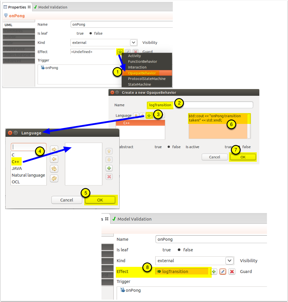
- Select the "OnPong" transition. In the Properties view's UML Tab, click on the [+] to the right of the "Effect" field to create a new action and select "Opaque behavior".
- In the resulting dialog, set the name to "logTransition".
- Click on the [+] to the right of "Language" to bring up the language selection dialog
- Double-click on "C++" from the selection dialog to move it to the selected item box. We are using C++ as the coding language within the tool to match our C++ runtime service library
- Click [OK]
- In the blank box to the right of the language selection, type "std::cout << "onPong transition taken!" << std::endl;". This log command will enable us to see when the transition is taken when running the resulting executable.
- Click [OK].
- The transition now contains an effect that will be executed each time the transition is taken.
Add the "Playing" entry action behavior to the state machine
We will now create an action that happens each time the "Playing" state is entered. This approach allows us to have this code in a single location, whether the transition into the "Playing" state is from the "initial" or the "OnPong" transition, allowing this player to both start the game and keep on playing, as per our requirements. This action will consist in sending a "ping" message to the other player, represented by the "Ponger"capsule. To do this, we'll add an entry action to that state to handle that.
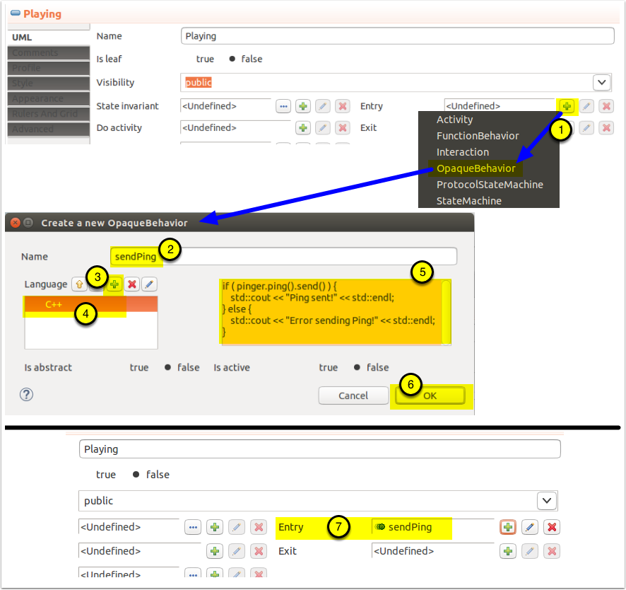
- Select the "Playing" state. In the Properties view's UML Tab, click on the [+] to the right of the "Entry" field to create a new entry action and select "Opaque Behavior", just like you did int the previous step.
- In the resulting dialog, set the name to "sendPing".
- Click on the [+] to the right of "Language"
- In the resulting dialog, set "C++" as the language, clicking [OK] to get back to the opaque behavior creation dialog.
- In the blank box to the right of the language selection, type the following code: if ( pinger.ping().send() ) { std::cout << "Ping sent!" << std::endl; } else { std::cout << "Error sending Ping!" << std::endl; }
- Click [OK] to get back to the Properties view
Note: the syntax to send a message on a port is "().'(').send()". In the case above, no parameters were defined for the "ping" protocol message. There are other variants of the send command that allows, for example, to send a message to one slot of a replicated capsule part. The "Send()" operation returns the number of messages sent, so returning "0", which is equivalent to "false", indicates an error.
Create the Ponger Capsule
The "Ponger" capsule will be created in the same way as the "Pinger" capsule was in the previous step. So the instructions below should be familiar to you, even when abbreviated.
Create the Ponger capsule
- Right-click on the PingPong model in the Model Explorer and select "UMLRealTime > Capsule"
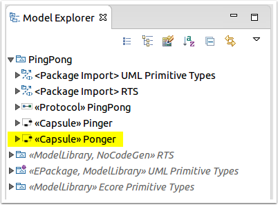
- Rick-click on the newly created capsule and select "Rename" to change its name to "Ponger"
Open Ponger's Composite Structure Diagram
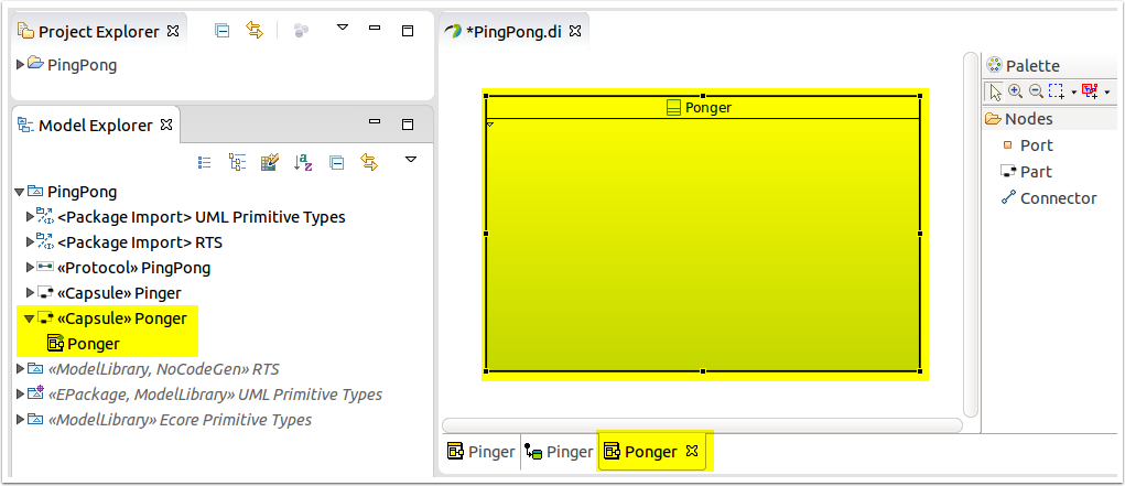
- Expand "Ponger" in the model explorer and double-click on the "Ponger" composite structure diagram to open it in the editor view.
Add a port to Ponger and set its type
Ponger will need to communicate with Pinger when it receives the ball, that is, it will have to respond by sending the ball back. To do this, it needs a port that implements the "PingPong" protocol we defined earlier.
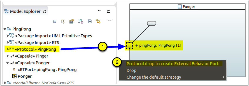
- In the Model Explorer, select the "PingPong" protocol and drag it to the left border of "Ponger" on the composite structure diagram.
- In the resulting dialog, click on "Protocol drop to create External Behavior Port"
Rename the port and set its conjugation
In order to be able to communicate, connected ports must have opposite conjugation. Since we left the conjugation of the "pinger" port in "Pinger" to the default, we have to change this port to be conjugated.
- Rename the port to "ponger".
- Click in the box to the left of "Is conjugated"
Add IO libraries
Just like we did with "Pinger", we will use the C++ standard "cout" to log messages, showing that the model is indeed executed.
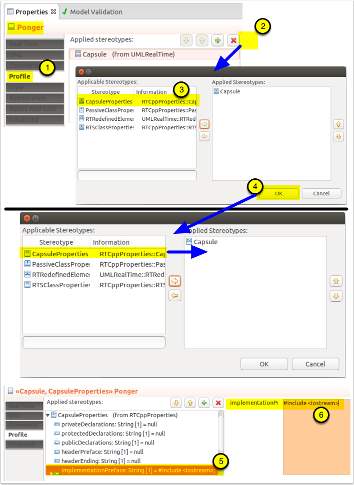
- Make sure that the "Pinger" capsule is selected and its Properties displayed with its "Profile" tab selected.
- Click on the [+], right of "Applied Stereotypes"
- In the resulting dialog, double-lclick on the "CapsuleProperties" entry in the "Applicable Stereotypes" box to move it to the "Applied Stereotypes" and click [OK] to apply the stereotype. This stereotype allows the modeler to set C++ specific constructs to help in the development of the executable model.
- Expand the "CapsuleProperties: stereotype to see its properties and select the "implementationPreface" property.
- In the "Implementation box, type in the following: #include
That's all we need for now, we will see how to use this import during the creation of the the capsule's behavior.
Create Ponger's state machine
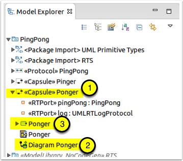
- Right-click on "Ponger" in the Model Explorer and select "New Diagram > StateMachine Diagram"
- In the resulting dialog, name the state machine diagram "Ponger" and click [OK]
- Rename the state machine to "Ponger"
- Both the state machine and its diagram are now available
Set the state machine's stereotype and properties
Note: The tooling does not yet set all the properties for a UML-RT state machine, so you will have to set them manually.
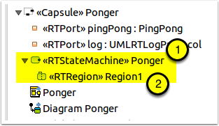
- Keeping the "Ponger" state machine selected in the Model Explorer, use the Profile tab of the Properties Explorer to add the "RTStateMachine" stereotype to the state machine.
- Expand the "Ponger" state machine in the Model Explorer to show and select the contained "Region1" region and then add the "RTRegion" stereotype to it.
1.
Create the state machine's content
The "Ponger" state machine will greatly resemble the one that we created for "Pinger". The main difference is that since "Ponger" will not be initiating the game, all its action can be defined as part of an "onPing" transition - there is no need to create an entry action in this case.
Similarly to "Pinger", the state machine for "Ponger" consists of a single state "Playing" with a self-transition triggered on receiving the "ping" message on the "ponger" port.
However, "Ponger" will not be initiating the game, so its action can be defined entirely as part of an "onPing" transition - there is no need to create an entry action in this case.
- Using the Palette's "Nodes" drawer, add an "Initial" pseudostate to the top left of the capsule's state machine and apply the "RTPseudostate" stereotype to it. You can leave its name as is or change it as you please.
- Using the Palette's "Nodes" drawer, add a "State" below and to the right of the "Initial" pseudostate, name it "Playing", and apply the "RTState" stereotype to it.
- Using the Palette's "Edges" drawer, draw a "Transition" from "Initial" to "Playing" named "initial", and another from "Playing" to itself named "onPing".
Note 1: The start and end are very important when drawing a transition and it defines the direction, the first click being the origin and the second the destination.* Note 2:* It is a good idea to name transitions as this helps in understanding the diagram and, also, in debugging later on - here, we have used a short form of the trigger event. Note 3: Setting the transition to be "rectilinear" is useful when drawing state machines: right-click on a transition and select "Format > Line Style > Rectilinear Style Routing.
Add "onPing:" transition trigger to the state machine
As indicated previously, the "Initial" transition does not need a trigger as it is taken automatically when the state machine is first instantiated. However, for the "onPing" transition to be taken, we will need to define a trigger for the transition that will determine when the transition can be taken.
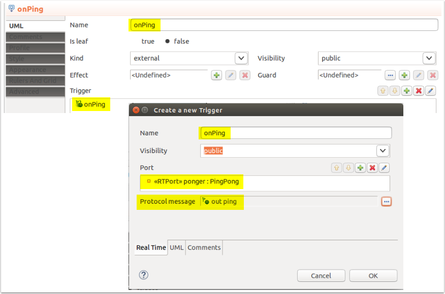
- Select the "onPing" transition. In the Properties view's UML Tab, click on the [+] to the right of the "Trigger" field to create a new Trigger.
- In the resulting "Create a new Trigger" dialog, set the name to "onPing".
- Click on the [+] to the right of the "Port"
- On the resulting dialog, find the "ponger" port under the "Ponger" capsule, double-click on it to transfer it to the right box
- Click [OK], closing the dialog and bringing back the "Create a new Trigger" dialog
- Click on the [...] to the right of "Protocol message" to bring up the "Protocol Message" dialog
- Select the "ping" protocol message.
- Click on [OK], closing the dialog and bringing back the "Create a new Trigger" dialog and then [OK] again to close that dialog
- The trigger is now complete and the results are shown below.
Add an effect to the "onPing" transition to log it was taken.
So that we can be sure that the "onPing" is indeed taken, let's add an effect to log this.
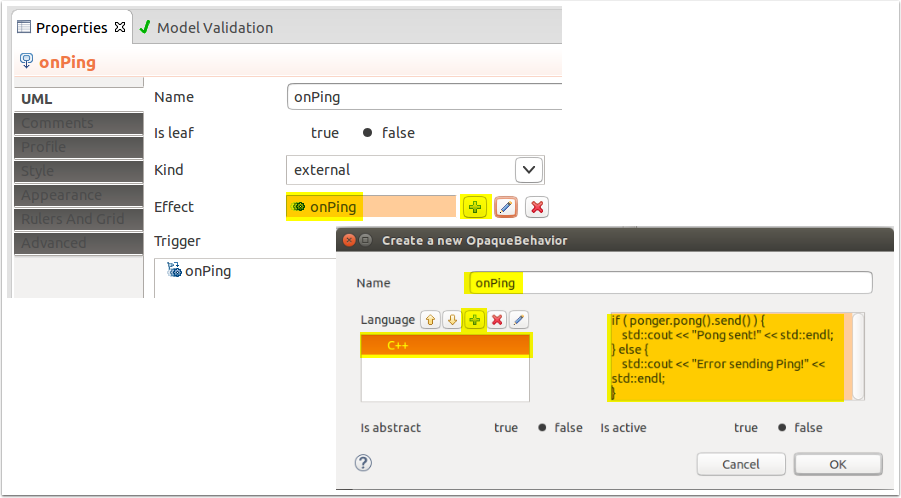
- Select the "OnPing" transition. In the Properties view's UML Tab, click on the [+] to the right of the "Effect" field to create a new action and select "Opaque behavior".
- In the resulting dialog, set the name to "logTransition".
- Click on the [+] to the right of "Language" to bring up the language selection dialog
- Double-click on "C++" from the selection dialog to move it to the selected item box. We are using C++ as the coding language within the tool to match our C++ runtime service library
- Click [OK]
- In the blank box to the right of the language selection, type the following code:
if ( ponger.pong().send() ) { std::cout << "Pong sent!" << std::endl; } else { std::cout << "Error sending Ping!" << std::endl; }
This will send back a pong message to "Pinger" and display a message indicating whether the send was successful or not. This enables us to see when the transition is taken when running the resulting executable. 1. Click [OK]. 1. The transition now contains an effect that will be executed each time the transition is taken and the results are shown below.
Implement the System as the Top Capsule
As described previously, the top capsule represents the system to be built. As such, it will not be contained in any other capsule and will contain the capsules required to implement its capabilities.
In the context of this tutorial, our Top capsule will contain instances of both "Pinger" and "Ponger" as well as the connection between them.
Note: At present, the top capsule must be named "Top". This is a limitation until we complete the implementation of the build specification mechanism.
Create the Top capsule
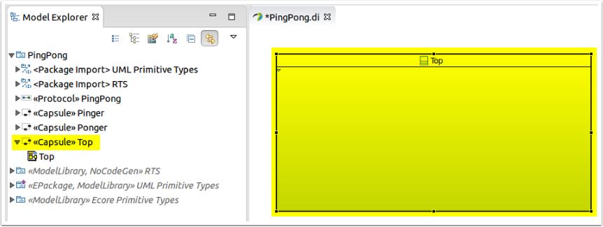
Using the steps from the creation of the "Pinger" capsule, create the "Top" capsule and its composite structure diagram, but stop before the creation of the port as "Top" does not require any ports.
- Right-click on the PingPong model in the Model Explorer and select "UMLRealTime > Capsule"
- Rick-click on the newly created capsule and select "Rename" to change its name to "Top"
- Open the composite structure diagram for "Top"
Add Pinger to the Top Capsule Structure
We can now start populating the "Top" capsule by creating an instance of "Pinger" within its structure.
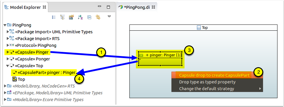
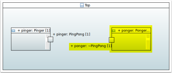
- Drag and drop "Pinger" from the Model Explorer inside of "Top"'s structure, on the left side.
- In the resulting dialog, click on "Capsule drop to create CapsulePart".
- You will see that the "instance" is called "pinger".
- Expanding "Top" in the Model Explorer reveals the new "«CapsulePart» piner:Pinger" property added to the capsule.
Fun fact: "pinger" is not an instance, but a "part". In this case the part contains a single instance of "Pinger". However, a part can have a multiplicity, and therefore contain multiple instances (or not if it's multiplicity has a lower bound of 0).
Adjust the representation of the pinger capsule part
Workaround: The tooling does not yet automatically show the ports of capsule parts, so you will have to do that manually.
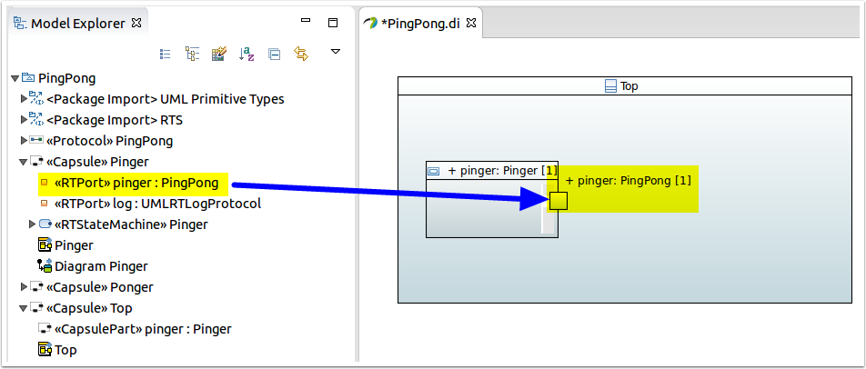
- In the Model Explorer, select the the "pinger" port under the "Pinger" capsule and drop it onto the "pinger" capsule part in Top.
- Move the port so it will be on the right side of the "pinger" capsule part.
Add Ponger to the Top capsule
- Repeat the steps you used to add "Pinger" to the "Top" capsule, but this time using the "Ponger" capsule.
Connect the two capsule parts
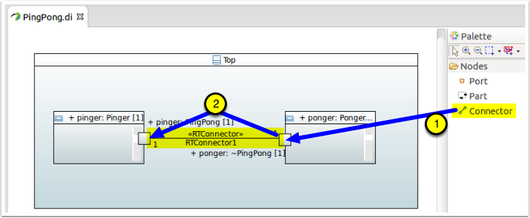
- Select the "Connector" tool from the Palette
- Draw a connector from one port to the other (it does not matter from which port you start).
Execute the model
Now that the model is complete, we can execute it.
Generate the code
Now that the model is complete, let's generate the code.
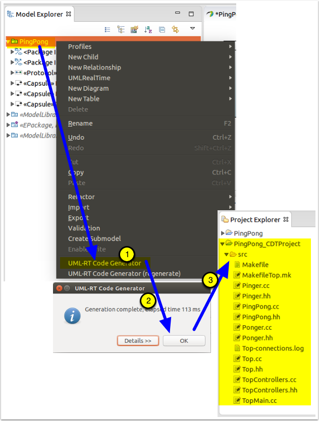
- Right-click on the model in the Model Explorer and select "UML-RT Code Generator"
- Click [OK] on the dialog that shows the results
- A CDT project is created and the C++ code is generated within it.
Setup the Build environment
In order to be able to compile and link the generated code, the build environment must be set up. The first requirement is regarding the compiler version supported out of the box by the RTS. Within Papyrus for Real Time v0.7.0, the RTS library was pre-built using g++ 4.7.2 (even though the configuration says 4.6.3...), so it is recommended to have that version installed as the default.
If you do not have g++ 4.7.2 installed and do not wish to install it, you can follow the instructions at Building the RTS
Compile the model
To compile and run the model, you will need a compatible build environment. At present, we support Linux.
The integration with CDT is not yet complete. To build the system, you will have to go to the command line.
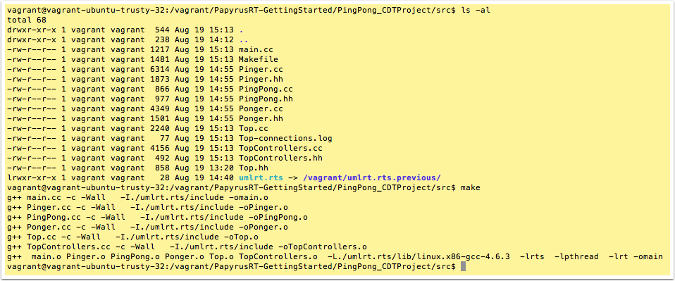
- Open a terminal and go to the folder where the code was generated, in this case, the folder name would be /PingPong_CDTProject/src, replacing "" with the path to your workspace location, e.g., "~/workspaces/GettingStarted".
- If there is no "umlrt.rts" folder in that location, you will need to create a link using ln -s /plugins/org.eclipse.papyrusrt.rts_/umlrts ./umlrts.rt where: is the path to the folder where Eclipse is installed, e.g. "~/Apps/Eclipse" is the latest version of the plugin, e.g., "0.5.0.201506181214"
- Type "make" at the command prompt to compile and link the model's generated code.
Run the model's executable
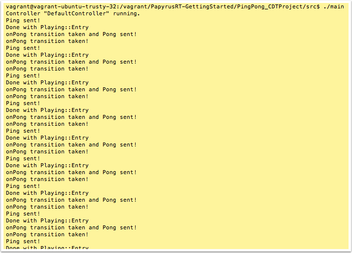
You can then run the executable, making sure to kill it soon after it starts, else it'll run forever...
- At the command prompt, type "./main"
- Quickly type "Ctrl-c" to kill the execution

