Notice: This Wiki is now read only and edits are no longer possible. Please see: https://gitlab.eclipse.org/eclipsefdn/helpdesk/-/wikis/Wiki-shutdown-plan for the plan.
Difference between revisions of "Papyrus/customizations/robotics/modular"
(Created page with "= Modular and Role based design = = Supported diagrams = == Component definition diagram == A component definition diagram models the internal structure and external interf...") |
|||
| (2 intermediate revisions by the same user not shown) | |||
| Line 6: | Line 6: | ||
A component definition diagram models the internal structure and external interface of a component. The former includes parameters, activities and functions, the latter ports that provide or require services | A component definition diagram models the internal structure and external interface of a component. The former includes parameters, activities and functions, the latter ports that provide or require services | ||
| + | |||
| + | [[Image:Papyrus-robotics-palette-component.png]] | ||
== Service definition == | == Service definition == | ||
| − | + | The goal of the service definition diagram is to defines services, as defined in the RobMoSys [https://robmosys.eu/wiki/modeling:metamodels:service service meta-model]: A Service allows interaction (i.e. regular exchange of information) between software components. A Service consists of service-properties (defined in an external metamodel) and a communication-pattern-usage. | |
| + | |||
| + | In the UML realisation, we have used the concepts of templates and template binding. A communication pattern is defined as a template with one or more formal parameters. A service definition binds the formal parameters to concrete communication objects, for instance the formal parameter ``Message'' of a Push pattern is bound to a concrete data type definition. | ||
== Datatype definition diagram == | == Datatype definition diagram == | ||
| − | This diagram is used to define data types, including | + | This diagram is used to define data types, including those with variable elements. |
| + | |||
| + | The Palette it shown below. | ||
| + | |||
| + | [[Image:Papyrus-robotics-palette-datatypes.png]] | ||
| + | |||
| + | The UML realisation is based on datatype definitions. | ||
| + | |||
| + | Not all data types are communication objects. In order to avoid duplicates, the palette of the diagram only enables the creation of the different data-type variants. At any moment, a data-type can be converted into a communication object and vice versa, as shown in the following dialog. | ||
| + | |||
| + | <center> | ||
| + | [[Image:Papyrus-customizations-robotics-ToggleCommunicationObject.png]]<br/> | ||
| + | Toggle between data-type and communication object | ||
| + | </center> | ||
| + | |||
| + | |||
== System assembly == | == System assembly == | ||
| − | A set of component instances that are | + | A set of component instances that are ''wired'' together via their ports. At this level, it is also possible to configure component instances. |
| + | |||
| + | [[Image:Papyrus-robotics-palette-system.png]] | ||
| + | |||
| + | The palette shown above enables the user to declare new component instances (besides the possibility to declare comments and constraints). After an instance is added, use the property view to assign a component type. | ||
| + | Once the type is assigned, parameter settings can be updated via the property view as well (provided that the component definition has assignable attributes). | ||
| + | |||
| + | After a type is assigned, the ports appear (choose a graphical position manually) and can be connected. | ||
Latest revision as of 16:32, 13 April 2019
Contents
Modular and Role based design
Supported diagrams
Component definition diagram
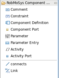
A component definition diagram models the internal structure and external interface of a component. The former includes parameters, activities and functions, the latter ports that provide or require services
Service definition
The goal of the service definition diagram is to defines services, as defined in the RobMoSys service meta-model: A Service allows interaction (i.e. regular exchange of information) between software components. A Service consists of service-properties (defined in an external metamodel) and a communication-pattern-usage.
In the UML realisation, we have used the concepts of templates and template binding. A communication pattern is defined as a template with one or more formal parameters. A service definition binds the formal parameters to concrete communication objects, for instance the formal parameter ``Message of a Push pattern is bound to a concrete data type definition.
Datatype definition diagram
This diagram is used to define data types, including those with variable elements.
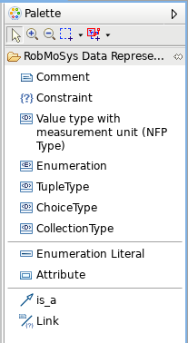
The Palette it shown below.
The UML realisation is based on datatype definitions.
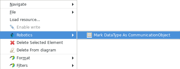
Not all data types are communication objects. In order to avoid duplicates, the palette of the diagram only enables the creation of the different data-type variants. At any moment, a data-type can be converted into a communication object and vice versa, as shown in the following dialog.
System assembly
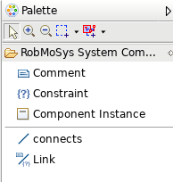
A set of component instances that are wired together via their ports. At this level, it is also possible to configure component instances.
The palette shown above enables the user to declare new component instances (besides the possibility to declare comments and constraints). After an instance is added, use the property view to assign a component type. Once the type is assigned, parameter settings can be updated via the property view as well (provided that the component definition has assignable attributes).
After a type is assigned, the ports appear (choose a graphical position manually) and can be connected.


