Notice: This Wiki is now read only and edits are no longer possible. Please see: https://gitlab.eclipse.org/eclipsefdn/helpdesk/-/wikis/Wiki-shutdown-plan for the plan.
Step 3: refine system requirements through a SysML model
Contents
- 1 Create new Eclipse project to host model
- 2 Create Papyrus SysML model
- 3 Identify use cases from functional requirements
- 4 Define traceability configuration
- 5 Define new traceability link type
- 6 Create Refinement link
- 7 Observe real time traceability
- 8 Delete traceability links
- 9 Visualize traceability tree for a given element
- 10 Complete traceability
Create new Eclipse project to host model
File menu>new>project...> general project and give name “SystemModeling”
Create Papyrus SysML model
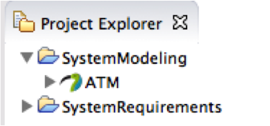
Select SystemModeling project Right click>new other...>Papyrus Model Give “ATM” as name (ATM.di), choose SysML language and click "finish". You should have ATM model that appears in project explorer view as below
Identify use cases from functional requirements
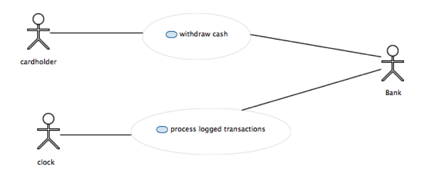
From the list of requirements we can identify two use cases:
- withdraw cash
- process transactions
Go in model explorer view, select model (root element) and right click>create new diagram>Create new Use cases diagram Give name "ATM use cases" and define it as below
Define traceability configuration
We want to trace our system requirements to model; for instance SYS-REQ-010 to our use case. We need to define a traceability link type for that purpose. Note: SysML provides a "refine" traceability link type but it can only be used between a SysML requirement and UML/SysML element. Here we get requirements that are not expressed in SysML language so we cannot use SysML notation for that link.
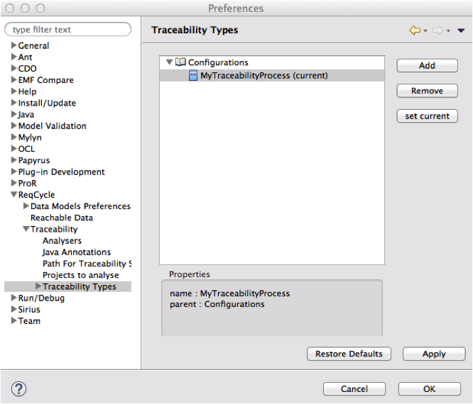
Let us create our traceability configuration and first link. Go to ReqCycle preferences (top ReqCycle menu>ReqCycle Preferences) Go to "Traceability Types" preference sub category and create a new traceability configuration through "add" button. Give name "MyTraceabilityProcess" and click "set current" button to enable it as the current active traceability configuration.
Define new traceability link type
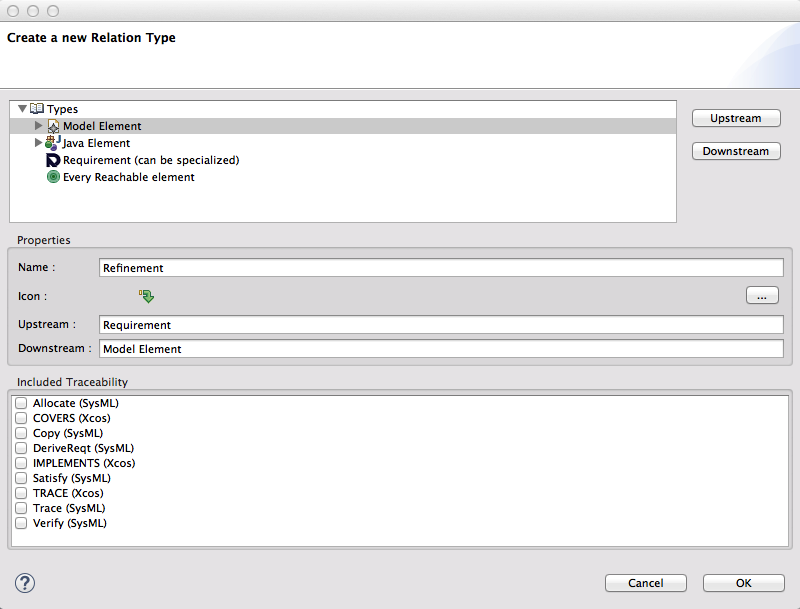
Select MyTraceabilityProcess configuration and use "add" button to create a new traceability link type. A new windows opens.
Give name "Refinement", select "Requirement" and use "upstream" button to define upstream (source) of link type. Select "Model" element and use "downstream" button to define "downstream" (target) of link type. Select first icon in the list.
Create Refinement link
Drag requirement "Sys-Req-010" from "Requirements" view to "Withdraw cash" use cases in model explorer view. A popup menu opens with possible link types available for this target selection (only one for now) Click on "Refinement" link type
Observe real time traceability
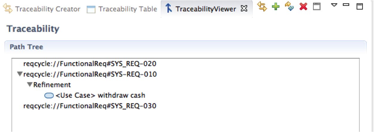
Go to Traceability table view: a new row has been created with link type "Refinement" , upstream that refers to the requirement and downstream that refers to the use case.
Delete traceability links
ReqCycle displays traceability links that you created and links that have been captured from existing models (for instance "satisfy link" in a SysML model. You can only delete the links that were created through ReqCycle, not the ones created in a modeling tool and captured by ReqCycle.
In order to delete links created in ReqCycle and also called "Transversal links" you first need to select a mode where you see only those transversal links (that is a little bit tricky and there is a bug to improve that). There is a button to push for that. When you have request to see only "transverse links" you can select a link and right click on it: a "delete" shall appear as context menu.
Visualize traceability tree for a given element
Select TraceabtilityViewer view. Drag and drop the first 3 requirements of "Requirements" view (including Sys-Req-010") in "path tree" area. Traceability tree is built automatically for each of those 3 requirements (you should see only one link for Sys_REQ-010 for now).
Complete traceability
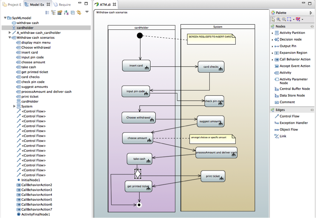
Now let us describe scenarios for our main "withdraw cash" use case. We use an activity diagram for that.
Note: we could also use sequence diagrams for that purpose but we would then need to define several diagrams to capture all paths whereas activity diagram can capture different scenarios and so provides better synthesis.
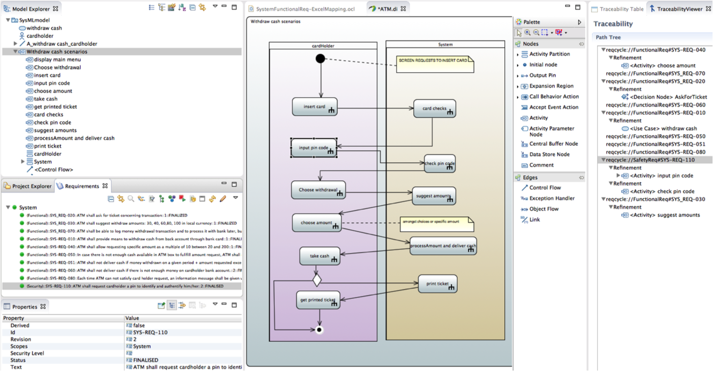
Now we can complete our traceability on activity nodes available in model explorer. We can check which requirements are traced by using TraceabtilityViewer.

