Notice: This Wiki is now read only and edits are no longer possible. Please see: https://gitlab.eclipse.org/eclipsefdn/helpdesk/-/wikis/Wiki-shutdown-plan for the plan.
SHARP Input Model
The key focus of the multi-physics coupling demonstration is to demonstrate reactivity feedback due to structural and mechanical deformation. In transient events in SFRs where the core heats up, thermal expansion causes the core to expand radially outward. The core restraint system is designed to force the assemblies to bow outward, enhancing the displacement and also the negative reactivity feedback effect. This promotes stabilization of the core power and prevents core damage. In particular, the Advanced Burner Test Reactor (ABTR) concept has been selected for analysis, because the data is widely available and the core restraint system is consistent with other reactors under consideration in the ARC program.
The SHARP toolset, developed under the NEAMS program, simulates the key coupled physics phenomena inside a nuclear reactor. For this ABTR demonstration problem, the following physics will be considered:
- Neutronics with Argonne's PROTEUS code,
- Fluid mechanics and heat transfer with Argonne's Nek5000 code, and
- Structural mechanics with LLNL's [DIABLO] code
These physics modules will be integrated using MOAB's framework and mesh generation will be performed with MeshKit. Each of the physics modules is based on either the finite-element or spectral-element methods.
For a particular physics module, the information we wish to describe can be broadly categorized as follows:
- Geometry
- Mesh (to be handled externally by MOAB)
- Materials (including material properties as well as other physics data that would be associated with the mesh)
- Boundary conditions
- Initial conditions
- Predicted results
In general, the data in each category will be different for each of the physics modules, although some data will be in common. This is where the coupling occurs, i.e. where the solution of one physics module influences the other modules. For example, the duct wall temperature calculated by Nek5000 determines the thermal expansion in DIABLO, which influences the neutron transport in PROTEUS. However, there is generally more data items that are distinct for each physics module than in common, thus the data hierarchy should be two-level, with the top level representing the physics module and the second level representing the five categories of information listed above. For example, the neutronics code PROTEUS has its own set of geometry, mesh, material properties, boundary conditions, initial conditions and predicted results. The exception is typically the geometry, which, for the most part, would be common to all three modules. However, the geometry in each physics code is not necessarily identical. For instance, the handling socket at the subassembly inlet does not necessarily require a detailed representation in the PROTEUS neutronics model, but it would certainly be required for the DIABLO structural mechanics module.
Geometry
In the case of the ABTR demonstration problem, the focus is on the SFR core and supporting structure, and does not include the primary or intermediate cooling circuits outside the core. The reactor may roughly be divided into three axial regions: lower support, core, upper support. In this context, the "core" refers to the section of the reactor with the hexagonal lattice of subassemblies, and everything inside the subassemblies. The lower support region would include the inlet nozzles and lower internal structure. The upper support region would part of the outlet plenum and upper portions of the restraint system. The representation of the core region will be very similar in the three physics modules. The neutronics module PROTEUS may have a simplified representation of the lower and upper support regions, and the thermal-hydraulics module Nek5000 may simplfiy the lower support region. In general, the structural mechanics module will require the sophisticated models of the geometry in the lower and upper regions of the reactor, as this dictates the subassembly bowing in the core.
The first step is to divide the reactor into the "core external" and "core" zones. The Core object describes anything within the lattice of hexagon subassemblies. The "core external" or Ex-Core object describes the lower and upper support zones, possibly including the core barrel, inlet and outlet plena. Moving beyond this to the remainder of the primary coolant system, i.e. to model heat exchangers and pumps, would likely require the development of additional objects to describe these zones.
Ex-Core (Core Externals)
The Ex-Core object represents the regions above and below the core, and describes the lower and upper support zones, possibly including the core barrel, inlet and outlet plena. (More to come.)
Core
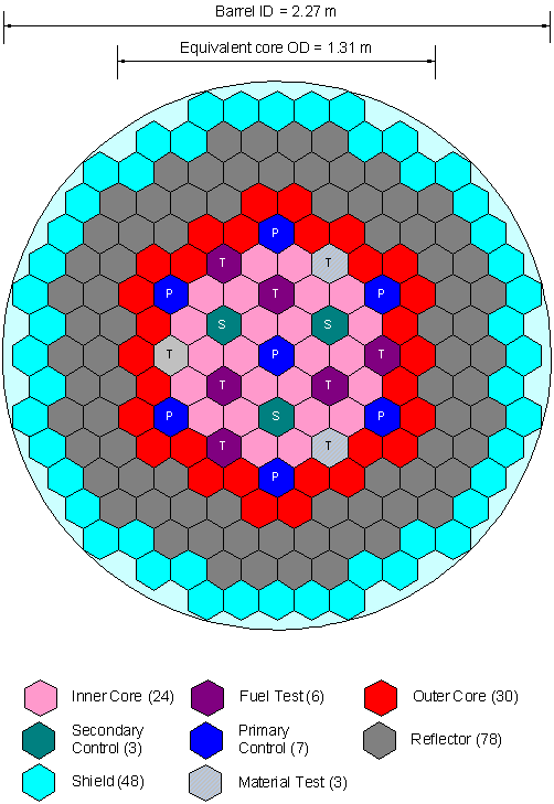
The SFR core is the highest level geometric entity provided in the ICE object model hierarchy. The SFR reactor core is modeled as a radial arrangement hexagonal assemblies. Convention dictates assemblies are ordered with the center-most assembly being "ring 1," the subsequent ring of assemblies surrounding it being "ring 2," and so forth, iterating in concentric circles outwards. Each SFR core contains <math>\scriptstyle 3\times(r^{2}~-~r)~+~1</math> assemblies, where r is the number of rows. The arrangement of the various subassemblies in the ABTR core is shown. The hexagonal subassemblies are grouped by color in the figure: the geometry inside each pink "inner core" subassembly are identical, as are the material compositions.
Objects of the Core geometry object include:
- Type (SFR)
- Size - Number of concentric assembly rows, starting with the center-most being row 1
- Symmetry Option - 1/3, 1/6, or full representation of the core
- Pitch - Nominal flat-to-flat subassembly dimension
- Length of Duct - Total length of duct
- Loading pattern - Type of subassembly loaded into each position in the core
Subassembly
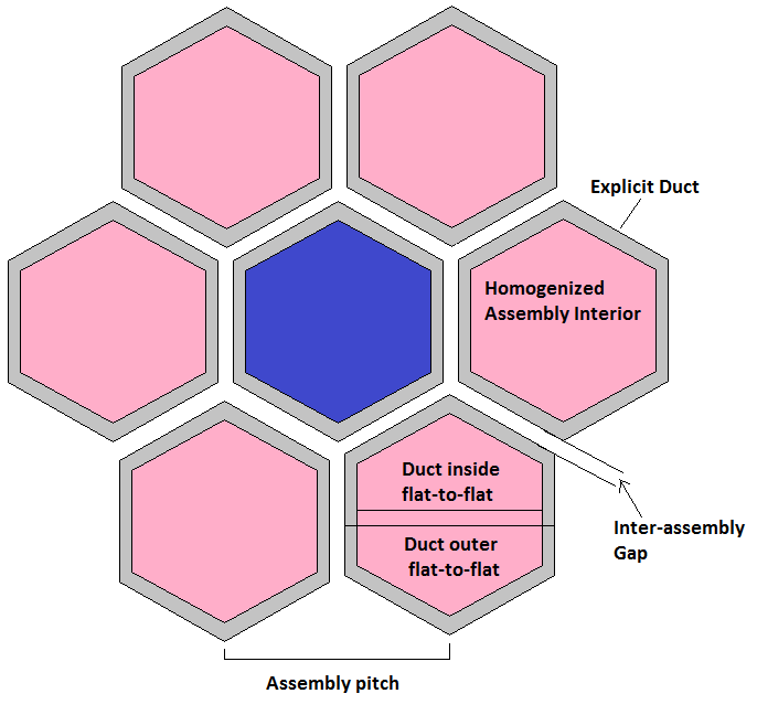
The radial core expansion phenomena is governed by the duct walls--along with the attached load pads, assembly inlet sockets, and core support structures--and not by the fuel pins or other structures within. Therefore, in the ABTR demonstration model, there will be no explicit representation of the fuel pins inside the subassemblies. Essentially, all geometric features inside the subassembly duct walls will be homogenized, including the fuel pins, wire wraps, gas plena, reflector and shielding structures. In the core region, only the hexagonal ducts will be represented explicitly. However, in order to calculate the homogenized compositions in each fuel assembly, the heterogeneous geometry is required.
The geometry is identical for of all subassemblies that are assigned the same type in the Core's Loading Pattern array. That is, for each enumerated type in the "Loading Pattern" array, there must be a Subassembly object to provide the additional geometric details.
Objects of the Subassembly geometry object include:
- Duct
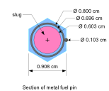
- Pin Section
Objects within Duct include
- Duct Outer Flat-to-Flat Distance
- Duct Wall Thickness
- Duct Inner Flat-to-Flat Distance = (Duct Outer Flat-to-Flat Distance) - 2*(Duct Wall Thickness)
- Inter-Assembly Gap = (Pitch) - (Duct Outer Flat-to-Flat Distance)
Objects within the Pin Section include
- Number of Pins
- Pin Pitch
- Outer radius of clad
- Inner radius of clad
- Fuel slug radius
- Wire rap radius
- Wire wrap axial pitch


