Notice: This Wiki is now read only and edits are no longer possible. Please see: https://gitlab.eclipse.org/eclipsefdn/helpdesk/-/wikis/Wiki-shutdown-plan for the plan.
Papyrus/UserGuide/ModelExecution
Contents
- 1 Moka Overview
- 2 Moka Releases
- 3 Getting started with Moka
- 4 FMI-based cosimulation in Papyrus
- 5 Designing FMUs with Papyrus
- 5.1 Configuration
- 5.2 Modeling and debugging FMUs
- 5.2.1 Basic principles
- 5.2.2 Reacting at an absolute date
- 5.2.3 Reacting at a relative date
- 5.2.4 Modeling computations
- 5.2.5 Modeling a periodic loop (v1)
- 5.2.6 Modeling a periodic loop (v2)
- 5.2.7 Reacting to a value change on an input
- 5.2.8 Reacting to an input change in an infinite loop (v1)
- 5.2.9 Reacting to an input change in an infinite loop (v2)
- 5.2.10 Loop with stop condition
- 5.3 Exporting an FMU
- 6 Available model libraries
Moka Overview
Moka is a Papyrus module for execution of UML models, which natively includes an execution engine complying with OMG standards foundational UML (fUML [1]) and Precise Semantics of UML Composite Structures (PSCS [2]). These standards deal with execution semantics of UML. Moka is integrated with the Eclipse debug framework to provide control, observation and animation facilities over executions. Moka can be easily extended to support alternative execution semantics, and thereby be adapted to multiple usage scenarios and domains. The key features of Moka are:
Based on standards
Moka provides basic execution and debugging facilities for fUML and its extension PSCS, which capture an executable subset of UML with precise and standard semantics. This subset is expressive enough to model structure and behavior of systems involving concurrent communicating entities, independently of technological platform details.
Interactive executions
Moka provides debug and animation facilities through a contribution and an extension to the Eclipse debug API. It is thereby possible to control execution of models(e.g., suspending/resuming executions after breakpoints have been encountered) as well as to observing states of executed models at runtime (e.g., emphasizing graphical views of model elements on which execution has suspended, retrieving and displaying any state information about the runtime manifestation of these model elements).
Extensible framework
Moka can be easily extended to address new execution semantics. This can be done through extension points enabling registration of executable model libraries (e.g., new MoCs, trace libraries, etc.) or simply tool-level extensions of the execution engine.
Moka Releases
Update sites
2019-03
- Nightly
- Releases
- Moka 4.0.0 - http://download.eclipse.org/modeling/mdt/papyrus/components/moka/2019-03
- Moka incubation features (FMI, Simex, ...) - https://download.eclipse.org/modeling/mdt/papyrus/components/moka/2019-03/incubation/
- Improvements
- Moka Core:
- Improved rendering of animation.
- Improved debugging environment.
- Moka tools:
- Simex: Set of accelerators to ease specification of executable models.
- Moka FMI
- FMI importer: Enables to import any FMU and give it a representation in a UML model
- FMI exporter: Enables to export FMUs from UML models (with some restrictions on the kind of supported model elements, and no support for rollback)
- FMI profile: Used for the representation of FMUs, and FMU assemblies
- FMI master : A generic master algorithm, capable of co-simulating a mix of imported/assembled FMUs and UML components (with behaviors specified as regular UML activities and/or state machines)
- Moka Core:
Getting started with Moka
Installation
From Marketplace
- Go Help - Eclipse Marketplace...
-
- Search "Moka" on the research engine
-
- Click on install.
- Accept the licence if needed and click on Finish.


Using Update Site
The process of installing Moka must be achieved following the steps described below:
- Go Help - Install New Software.
-
- Add the Nebula update site to the list of available update sites.
- Add the Moka update site to the list of available update sites.
-
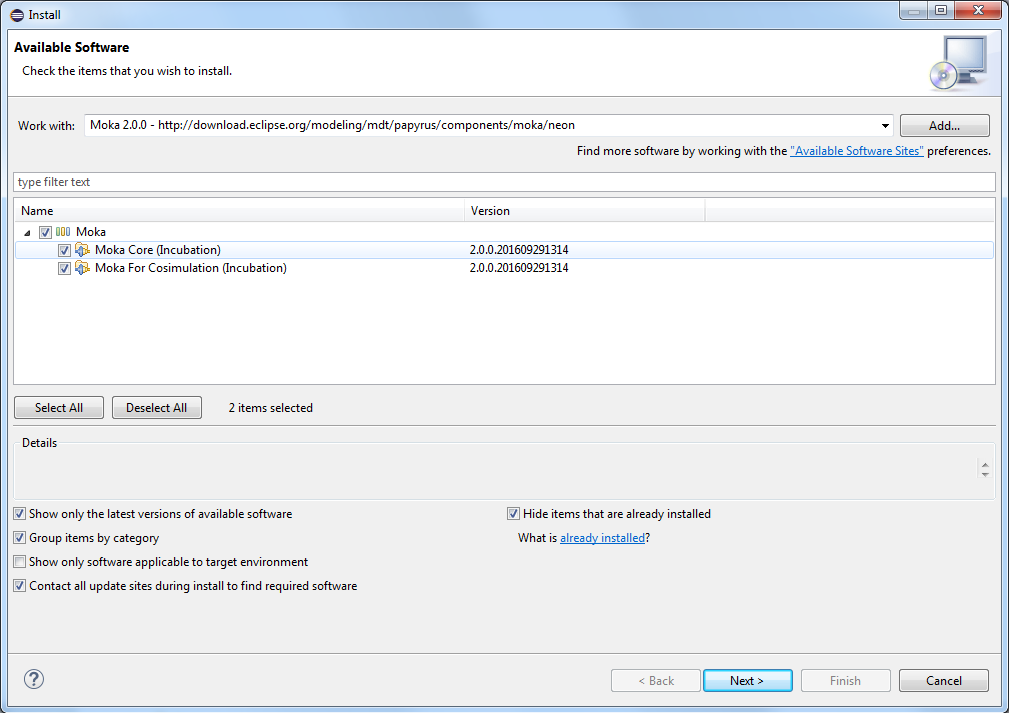
- Select the Moka feature(s) you would like to install and click Next.
- Moka provides two features:
- Moka Core: Provide the basics software components to perform model execution. Execution engines, debugger and animator are included in that feature.
- Moka for Co-simulation: Provide the software components implementing a support for FMI in Moka.
-
- Moka provides two features:


Your first executable model
This tutorial is based on a simple executable model. It consists in an active class, with a classifier behavior that indefinitely increments a counter. The corresponding Papyrus model is available here File:BasicActiveObjectExample.zip. Download it, define a project in your workspace, and then import the model in this project. Once the model is imported and open in Papyrus, the Increment class should look like:

The behaviors associated with this class (i.e., IncrementClassifierBehavior, which is the classifier behavior, and incrementMethod, which is the implementation of operation increment) are specified by activity diagrams. Corresponding activities are executable, according to the semantics given in OMG standards fUML and PSCS. Anyway, in fUML and PSCS, the execution of a model usually starts by executing a kind of "main" activity, which is responsible for instantiating objects, and stimulate them if needed (through signals or operation calls). Moka provides some facilities to generate this kind of activities. Just right click on class Increment, then go to Moka / Modeling Utils / Generate Factory.

A factory activity for class Increment (Increment_Factory in the figure below) is then generated. This activity will be used in the next steps of this tutorial to actually start the execution of the model. Do not forget to save your model, otherwise the factory will not be visible in the launch configuration definition step described below in this tutorial.

A behavior for the "<<Create>> Implement" method should be implemented. The "create method" menu could be use [screenshot].
Validation
fUML, PSSM and PSCS validation rules have been implemented in the tool.
Run Validation
To run the validation on the model:
- In the model Explorer right click on the model element
- Select the "Validation" menu
- In the sub menu select "Validate model" item
When there are errors the Model Validation view is open showing every validation errors and warnings, moreover markers are displayed in the model explorer and diagrams.
Validation constraints can be enabled or disabled using the preference page:
- In Eclipse, go to Window > Preferences
- Unfold the Model validation category
- Select the Constraints item
Validate before simulation
Moka validation rules are run before the simulation. If errors are detected the following pop-up is display.

It is thereby possible by:
- selecting the CheckBox, disable this functionality for further simulations
- clicking on the <<Details button, show or hide validation rules which are in error
- clicking on the Create Markers button: create marker on the model and diagrams
- clicking on the Cancel button: cancel the simulation
- clicking on the OK button: continue the simulation
Preferences
This functionality can be enabled or disabled using the preference page:
- In Eclipse, go to Window > Preferences
- Unfold the Papyrus category and select the Simulation item
- Select (enabled) or unselect (disabled) the checkbox

Referencing the mqtt server
Since Moka use a mqtt server for communicated with services, it is necessary to have a mqtt server install on the computer, for example mosquitto (available here). Before starting an execution, you should make sure that the mqtt server is referenced in eclipse. To do so, go to Eclipse preferences, as shown in the figure below.

Once the preference page is open, go to Papyrus/Simulation (Moka) item. In the "Server path" zone you should browse to the mqtt exe file.

Starting an execution with a launch configuration
Moka is integrated with the Eclipse Debug Framework. It implies that, in order to start an execution, a launch configuration has to be defined. A launch configuration can be created by clicking on the "Debug As" tool from the Eclipse tool bar, and then by pressing Debug Configurations.

Then create a new Moka launch configuration, as shown in the figure below.

A Moka launch configuration requires tree pieces of information: the UML model from which the execution will be started, the actual model element to be executed, and the execution engine to use.

Press the Browse button to select a UML model from your workspace (a .uml file shall be selected). Then, select the actual model element to be executed in the list "Element to be executed". This list is sorted alphabetically, by qualified names. Note that, in the case of the fUML and PSCS execution engines provided by Moka, the "Element to be executed" shall be an Activity. Finally select the engine you want to use, since Moka is an extensible execution framework, multiple execution engines can be registered in your environment. Your launch configuration should now look like:

To start the execution, simply press the Debug button. In our example, according to the semantics of PSCS, the effect of executing activity Increment_Factory will be to instantiate an Increment object, to construct this object (please refer to the default construction strategy described in the PSCS specification), and then start its classifier behavior. Our increment object will start to increment, and will go on until you stop the execution.
Note that a Launch configuration is a persistent artifact, so that, if you close Papyrus and then open it again, your launch configuration will still be available, and you will be able to relaunch it.
Managing breakpoints
In order to easily observe and control the state of you model at some specific points of the execution, Moka lets you associate breakpoints with model elements. This can be done through the contextual menu Moka/Debug, which is available from the model explorer and from diagrams.


Once a breakpoint has been created, a small icon (blue circle) appears on top of the corresponding model element.

Using the Moka/Debug menu, an existing breakpoing can also be de-activated (without being removed), using the "Toggle breakpoint activation" button. In this case, it will be depicted by a small white circle on top of the corresponding model element.

The set of existing breakpoints (as well as their status - Enabled / Disabled) is given in the breakpoint control panel, which is usually located in the upper, righ-hand part of the Debug perspective.

The breakpoint control panel more generally lets you enable, disable and remove breakpoints. Just right click in the panel, as depicted in the figure below.

From an execution standpoint, it is important to note that the selected execution engine (see section on "Selecting the execution engine") is responsible for interpreting breakpoints. In the case of the fUML and PSCS execution engines provided by Moka, only breakpoints associated with activity nodes or edges will be taken into account (even if Moka lets you associate breakpoints with any kind of model element). Other breakpoints are simply ignored.
Controlling Executions
Executions can be controlled using the execution control panel, provided by the Eclipse Debug perspective.

It is thereby possible to resume, suspend, stop, or even do step-by-step executions. Note also that, when execution is suspended, variables may be observable in the variable panel.

The selected execution engine is responsible to determine what the visible variables are in the context of an execution. In the case of the fUML and PSCS engines provided by Moka, visible variables are properties of the context object in which in the suspended activity is executing (in our example, the suspended activity is the classifier behavior of class Increment, which executes in the context of a particular Increment object, which holds a value for property counter).
Configuring animation
By default, Moka is configured to animate diagrams during executions, without automatically giving focus / making visible a diagram where a model element being executed has a graphical representation. This can be configured in the Animation control panel, which is available in the Debug perspective.

The slide bar enables to control the artificial animation delay between two animation steps. Note that option "Open diagrams automatically" may decrease performances of the execution engine. By default, Moka is released with some default animation styles, which determine the emphasis style to be applied to graphical elements when the execution is suspended, or more generally for animation. This default style can be overloaded per diagram, by attaching a CSS style sheet, as depicted in the figures below.


Error Detection
Moka provide a system of detection of error in the model, for example if during the simulation there is a empty token which is throw by an output pin this will necessary mean to an error. In this case the simulation is suspend, so you can visualized the state of the simulation:

- a message display the reason of the thread suspension
- the state of the system is available in the Variables view
- the element on which the element is stopped is displayed and coloured in orange
After understanding the reason of the suspension the simulation can be resume or stop as for a breakpoint suspension.
FMI-based cosimulation in Papyrus
Section under construction. Please follow this tutorial video
Designing FMUs with Papyrus
Configuration
After installation of Moka, a few configuration steps are required before starting this tutorial.
Activation of the Papyrus viewpoint for executable modeling
Moka provides a dedicated Papyrus viewpoint to ease executable modeling. It includes simplified palettes for class, composite structure, and activity diagrams. We recommand to use this viewpoint to improve the user experience. Before creating your first model, the viewpoint shall be activated as follows:
- From the Eclipse menu, click on Window / Preferences
- In the Preferences popup, open the Papyrus item, then select item « Viewpoints Configuration »
- In section « Configuration selection », select « Deployed through the extension point »
- In section « Viewpoint selection », select « Simex Designer » in the « Stakeholder » list, and « Simex Viewpoint » in the « Viewpoint » list. The resulting configuration looks like:

Activation of the Papyrus Perspective
Papyrus provides an Eclipse perspective for UML modeling. This perspective is not activated by default after installation. It shall be activated as follows:
- From the Eclipse toolbar, click on Window / Perspective / Open perspective / Other
- In the dialog, select Papyrus
Modeling and debugging FMUs
This section describes the principles for modeling and debugging FMUs with Papyrus, through several model examples. Each sub-section reminds the main points illustrated in the tutorial videos available on the Papyrus Youtube channel. The videos provide a step-by-step guide to create the various models.
These examples are directly available in a model provided with Papyrus/Moka. To retrieve the model :
- Step 1: If a project is already available, follow directly step 2. Otherwise, create a new project from the project explorer, as illustrated in the figures below:


- Step 2: From the project, righ click, and select New Example as illustrated below


- Step 3: select FMU Tutorial Model Example from the wizard, as illustrated below
The model contains 10 numbered packages. Each package corresponds to examples described in the following subsections.
Basic principles
This section summarizes the main points illustrated in tutorial video 01 - Creating an FMU.
Modelling
- Step 1: Creation of the project
- From the project explorer, right click, then New / Papyrus Project
- From the wizard, select UML as the modeling language
- From the following wizard, name the project and the model
- From the following wizard, name the root element of the model
- Step 2: Applying the FMI 2.0 profile on the model
- In the model explorer, select the model created at step 1 (a)
- Select tab « Profile », click on button « Apply registered profile », select « FMI 2.0 Profile », then check FMIProfile in the wizard.
- Step 3: Importing model libraries
- Right click on the model from the mdoel explorer, then Import / Import Registered Package
- Select FoundationalModelLibrary in the wizard. This library is defined as part of the OMG standard fUML. It provides basic functions (arithmetics, logic, etc.) useful to describe FMU behaviors..
- Repeat the Operation to import library UMLPrimitiveTypes, which defines UML basic types (Integer, Real, Boolean and String), used to type inputs and outputs of FMUs, as well as internal variables.
- Step 4: Creating an FMU
- In a class diagram, create a new Class. This class represents the FMU. It will be, in the end, the exported element.
- This class shall be active (Note: in fUML, the instanciation of an active class implies the start of its behavior). Property « is active » is available in the property view associated with the class. It must be set to « true ».
- Apply stereotype CS_FMU (which stands for Co-Simulation FMU), in order to identify that this class actually represents an FMU.
- Step 5: Defining the FMU’s behavior
- From the model explorer, select the classe, then right click, New Diagram / New Activity Diagram
- Once the activity is created, select the class again from the model explorer, select the « Advanced » tab of the property view. In the « Classifier Behavior » field, select the activity created previously.
- Step 6: Defining inputs and outputs of the FMU
- Create a new port on the class representing the FMU
- Type the port with one of the following UML primitive types: Integer, Real, String, Boolean.
- Select the port, select the stereotype tab, and apply stereotype « Port » (cf. step 2 about stereotype application).
- Assign a direction to the port (in or out)
- Set the value of field valueReference with an integer. Note : Each port of the FMU shall have a unique valueReference
Debugging
- Step 1: Switch to the Moka Debug perspective
- Step 2: Define a new Moka launch configuration
- In the « UML Model » field, select the .uml file containing the FMU to be executed
- In the « Element to be executed » field, select the FMU that you want to debug
- In the « Execution Engine » field, select org.eclipse.papyrus.moka.fmu.engine.debug
- Click on Apply, and then Debug to launch the execution.
- Step 3: Controlling the execution of the FMU
- Once the launch configuration is started, a dialog box appears, as illustrated below. This dialog box provides a simple interface which enables the user to act as a master for the FMU.

- Click on button Init to start the execution of the FMU’s behavior. Inputs and Outputs are initialized with default values provided in the model.
- Click on button Step to perform a simulation step. The step time size is determined by field Step size. This value can be changed by the user between two simulation steps.
- To modify the value of an input before a simulation step, click on the name of the port in the « name » column, and edit the value in the « value » column. Note : a semantic check is performed when entering the value. If the value is incorrect (for example, an integer is given while a boolean is expected) the « step » button is deactivated.
- When the user closes the window, the simulation stops.
Reacting at an absolute date
This section summarizes the main points illustrated in tutorial video 02 - Modeling reactions at absolute dates in an FMU .
Modeling a reactive behavior requires an AcceptEventAction in the activity defining the classifier behavior of the FMU:
- Step 1: Creation of a TimeEvent
- From the model explorer, right click, New Child / TimeEvent
- Select the TimeEvent in the model explorer, and switch to the UML tab in the property view
- In the « When » field, click on icon « + »
- In the popup, field « Expr », click on icon « + », and select LiteralReal
- In the next popup, field « value », put the absolute date as a real (e.g., 2.0)
- Step 2: Creation of an AcceptEventAction
- In the activity diagram of the FMU’s Classifier Behavior, create a new AcceptEventAction
- On the « trigger » field, click on icon « + »
- In the popup, field Event, click on icon « … »
- In the following popup, select the TimeEvent created at the previous step
The figure below illustrates a behavior modeled according to these principles, where the FMU starts its execution, interrupts until date 2.0, and then terminates its execution.

Reacting at a relative date
This section summarizes the main points illustrated in tutorial video 03 - Modeling reactions at relative dates in an FMU .
The modeling pattern is the same as for a reaction at an absolute date, except for the following point: for the TimeEvent, set the « Is Relative » field to true. The figure below illustrates a behavior modeled following these principles, where the FMU starts its execution, interrupts until date 2.0 (absolute TimeEvent), intterupts for 0.5 additionnal time units (relative TimeEvent), and then terminates its execution.

Modeling computations
This section summarizes the main points illustrated in tutorial video 04 - Some basic computation in an FMU.
In the example described below, computations are grouped inside an operation in order to improve readability of the model. However, they could have been specified directly in the Classifier Behavior of the FMU.
- Step 1: Declaring the operation
- In the class diagram of the FMU, create a new operation on the FMU using the palette.
- Select the Operation, and add required parameters through the property view. Parameters must be named, typed, and have a direction (in, out, or return). For output parameters, the operation can have either a single parameter with direction « return », or 1 or more parameters with direction « out » (Note: These constraints are imposed by OMG standard fUML). In the example illustrated in the figure below, FMU A owns an operation « test », with one input parameter « threshold » of type Integer, and one output parameter (return) of type Boolean.

- Step 2: Implementing the operation
- In the model explorer, select the operation created at step 1.
- Right click, then Moka / Modeling Utils / Generate Method. An activity is generated (in the example, testImpl), but not the corresponding diagram. The activity is automatically and formally linked with the operation. It provides its implementation.
- Select the activity in the model explorer, then right click, New Diagram / New Activity Diagram. This diagram can be used to specify the implementation of the method, as illustrated in the tutorial video. The figure below illustrates an implementation where the value of input x is compared to the threshold argument, and where the result of the comparison est returned. The value of x is taken by combining a ReadSelfAction (« self » in the example, which returns a reference to the context FMU) and a ReadStructuralFeatureValueAction (« readX » in the example, which refers to port x in the model). Function « greather than » is called via a CallBehaviorAction (« call> » in the example).

- Step 3: Calling the operation
- In the activity diagram of the FMU’s classifier behavior, add a CallOperationAction for the operation created at step 1 (Note : the action can be added with a drag’n’drop, as illustrated in the tutorial video)
- Add actions and objectFlows (i.e. links) to provide required arguments to the operation call.
- Add actions and objectFlows to exploit results of the operation call. In the example, the result of the call is assigned to output y, by using an AddStructuralFeatureValueAction (« setY »), as illustrated in the figure below.

Modeling a periodic loop (v1)
This section summarizes the main points illustrated in tutorial video 05 - Modeling Periodic Loops in an FMU (Variant 1).
In order to model a periodic loop, we rely on a Merge Node to form a loop in the control flow, and an AccepEventAction with relative TimeEvent to specify the period. In the example below, we periodically compare the value of input x with threshold 2 (via a call to operation test), and we assign the result of the comparison to output y. The period is 0.5 time units.

Modeling a periodic loop (v2)
This section summarizes the main points illustrated in tutorial video 06 - Modeling Periodic Loops in an FMU (Variant 2).
In fUML, when an AcceptEventAction has no input flow, it is automatically ready to fire again after a stimuli (at least if the activity is not explicitly terminated by a FinalNode). This principle is used in the example illustrated in the example below. It specifies a periodic loop functionnaly equivalent to the example described in the previous section.

Reacting to a value change on an input
This section summarizes the main points illustrated in tutorial video 07 - Modeling reactions to changes on FMU input values.
Modeling a reaction to a value change on a input relies on an AcceptEventAction. This is similar to modeling a reaction at an absolute or relative date, except that we use a ChangeEvent instead of a TimeEvent. To create a ChangeEvent:
- From the model explorer, right click, New Child / ChangeEvent
- Select the ChangeEvent in the model explorer
- In the property view, field « Change Expression », click on button « + », and select « LiteralString »
- In the popup, field « Value », type the name of the observed input.
The example below illustrates a behavior with a reaction to a change on input x. When the change is detected, the execution suspends for 0.5 time units, the value of x is compared to threshold 2, and the result of the comparison is assigned to output y.

Reacting to an input change in an infinite loop (v1)
This section summarizes the main points illustrated in tutorial video 08 - Modeling infinite change reaction loops (variant 1).
As for periodic loops, the loop model relies on a MergeNode. An AcceptEventAction with ChangeEvent is placed in the loop formed around the MergeNode. The example below illustrates this modeling pattern. The behavior described in the previous example (where the FMU reacts to changes on input x) is thereby repeated indefinitely.

Reacting to an input change in an infinite loop (v2)
This section summarizes the main points illustrated in tutorial video 09 - Modeling infinite change reaction loops (variant 2).
As for the second variant of periodic loops, the infinite change reaction loop can be simplified by suppressing the MergeNode, as well as input flows of the AcceptEventAction. This modeling pattern is illustrated in the figure below. It is functionally equivalent to the previous example.

Loop with stop condition
This section summarizes the main points illustrated in tutorial video 10 - Modeling a loop with stop condition.
The loops modeled in previous examples are infinite. This section describes how to add a stop condition. This can be done with a DecisionNode. There are multiple ways of using Decision Nodes. We present the simplest one:
- Provide the value to test as an input of the DecisionNode, using an ObjectFlow edge.
- Add outgoing edges on the DecisionNode. One of these edges shall (directly or indirectly) form a loop with the MergeNode
- A guard is specified for each of the outgoing edges. In the simplest case (presented here), the input value of the DecisionNode is a boolean value. Guards associated with outgoing edges shall be LiteralBooleans (« true » ou « false »). At execution time, the input value of the DecisionNode is compared to the values of guards on outgoing edges. When the input value equals one of the guards, the execution engine selects the corresponding edge. In fUML, if multiple outgoing edges can be selected, the choice is not deterministic. Note that in the implementation of Moka, the first matching edge is selected (the evaluation order depends on the order of creation of edges in the model). To create a guard on an outgoing edge:
- Select the edge
- In the property view, field « Guard », click on button « + », then select « LiteralBoolean ».
- In the popup, select True or False
In the example illustrated below, we use the result of CallTest to determine if stay in the loop (i.e., in the case where x is lower than threshold 2).

Exporting an FMU
In order to export an FMU :
- In the model explorer, select an FMU
- Right click, Moka / FMI / Export FMU for Co-Simulation, as illustrated below.

- The dialog box (see below) enables to:
- Specify the name of the FMU (by default, the name of the FMU in the UML model)
- The target directory for the exported archive
- The target execution platform (Linux 32, Linux 64, or Windows 64)
- To specify if a JRE shall be included in the archive (in order to get a fully standalone FMU).

Available model libraries
A generic controller for Active Objects
Stimulate your active objects with signals and observe their reactions