Notice: This Wiki is now read only and edits are no longer possible. Please see: https://gitlab.eclipse.org/eclipsefdn/helpdesk/-/wikis/Wiki-shutdown-plan for the plan.
ICE Mesh Editor Prototype
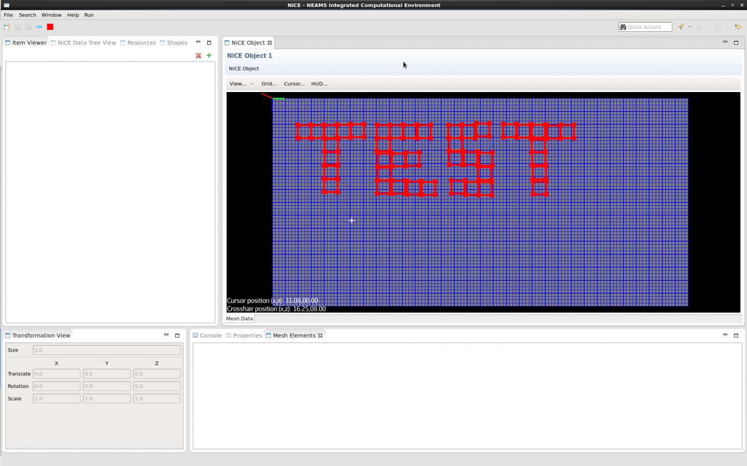
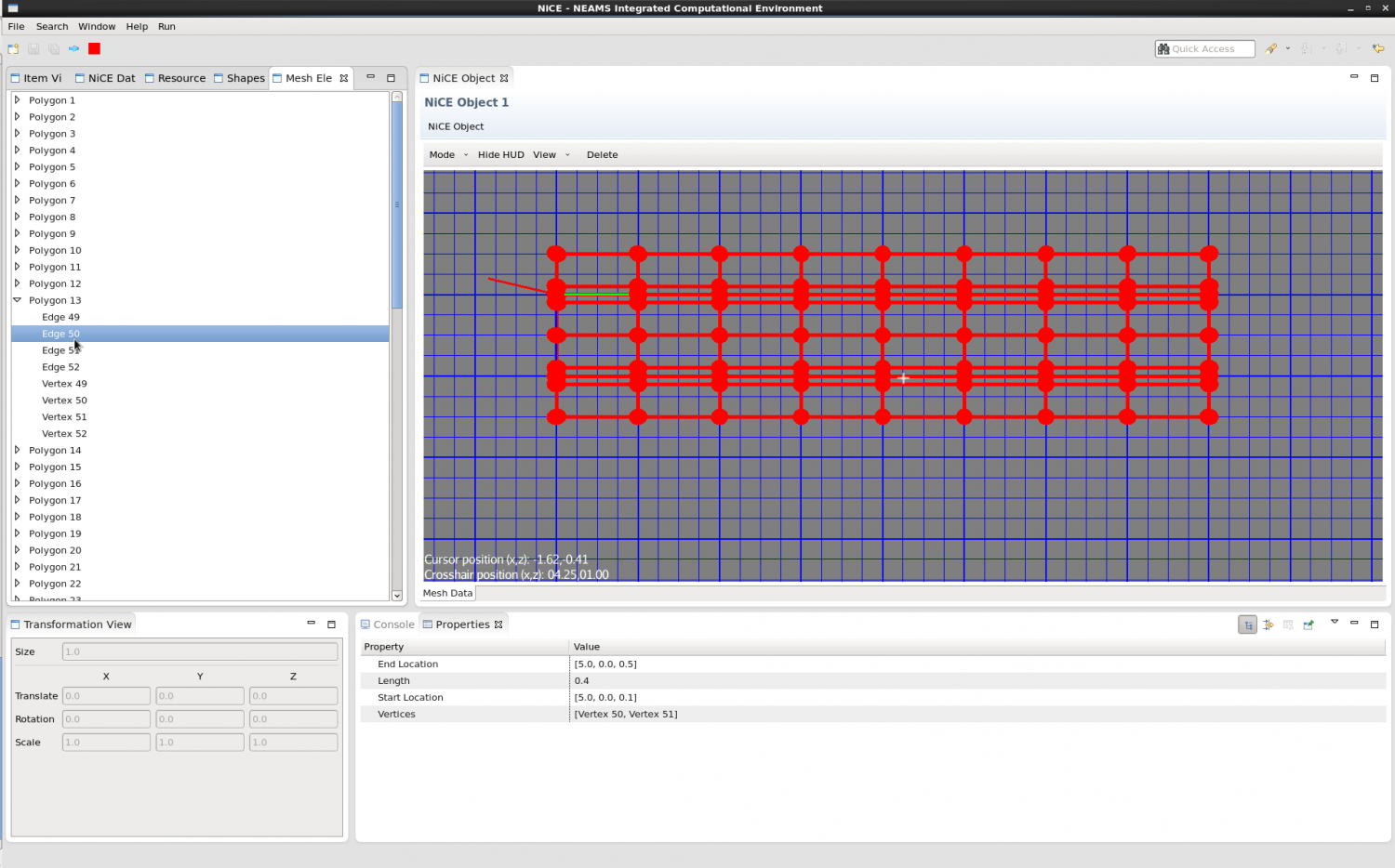
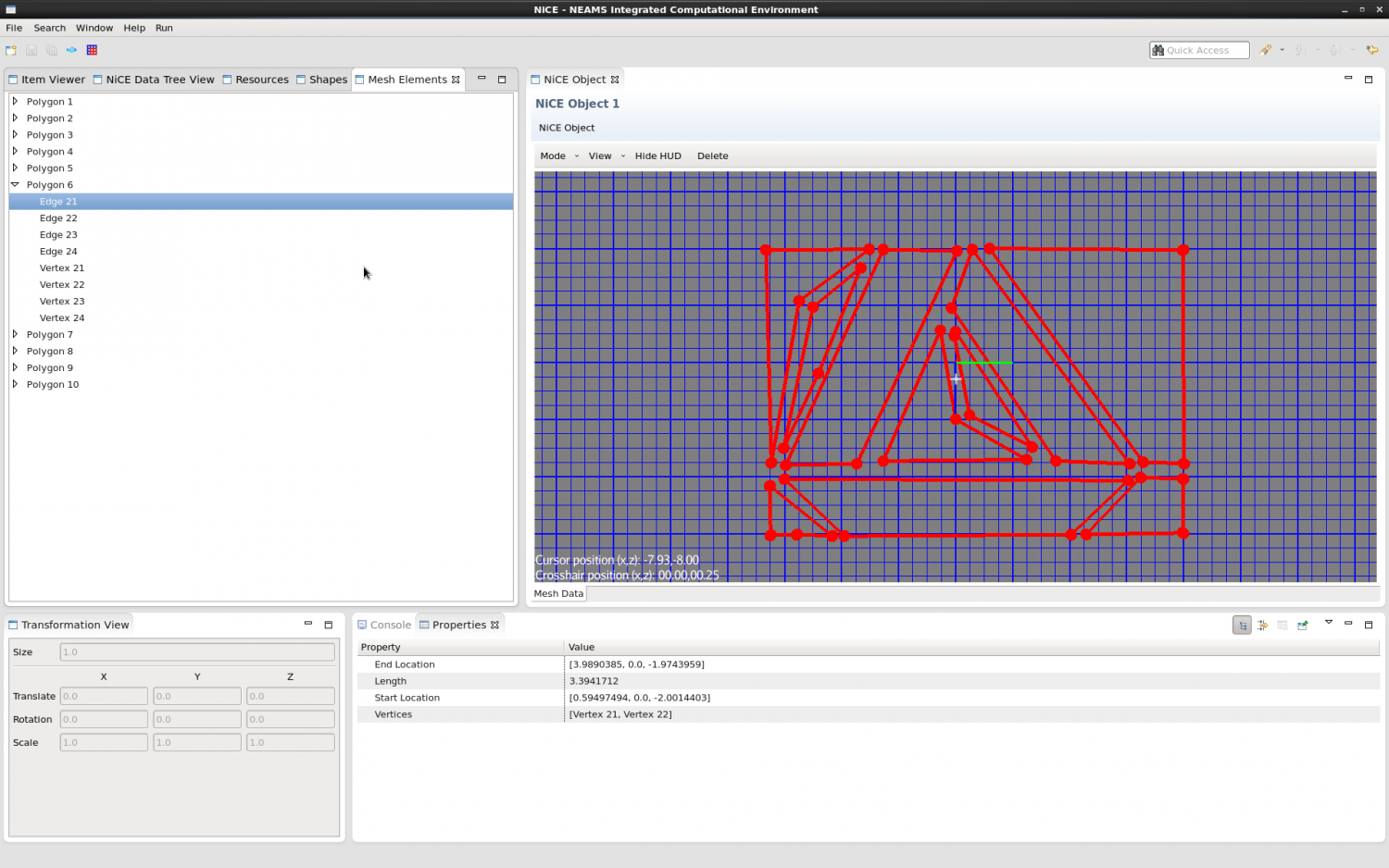
This page serves as a starting point for discussion of the new prototype Editor for generating 2D meshes for Nek5000. A new Editor in ICE will be created, and it will use jMonkeyEngine 3 to create 2D meshes. The code for this prototype is being maintained on the repository at code/branches/jME3MeshEditor/.
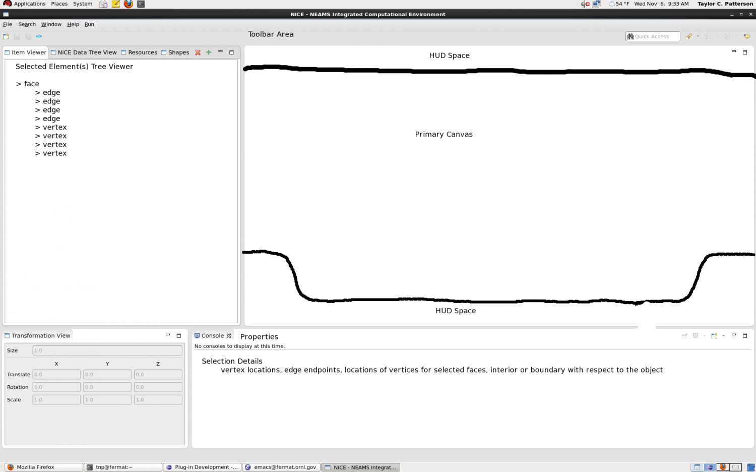
Eclipse Views
Notes
Primary Canvas
This region will be devoted to the jME3 mesh editor area. It will feature a background grid over which objects will be drawn.
Toolbar
An area for object, camera, cursor, and background canvas manipulation tools.
Heads-Up Display Component
Region for displaying frequently changinging data. (See the corresponding section below.)
Selected Element(s) Tree Viewer
A view to display the hierarchy of a selected element or elements. An element or part of an element (edge or vertex) may be selected from this list view or from the primary canvas. Selections should be reflected in the tree view and the primary canvas. The details in the properties view should be updated appropriately, as well.
Properties View
An area to display data about currently selected geometry components.
jMonkeyEngine 3
A playground for the prototype is available in the repository under code/seeds/gov.ornl.nice.jme3.terrainTest.
Primary Components
Below are the primary components the user sees and/or interacts with in the jME display.
- Player - The player is restricted to the terrain grid. When the player moves, the camera should move with the player. You can consider the player to be at the very center of the camera's frustrum.
- Camera - Centered on and locked to the player, the camera looks down on the xz-plane. It can be zoomed in and out.
- Cursor - The cursor is the primary interaction tool available to the user. It can be moved freely, but it should generally be visible to the camera.
- Grid - The grid is the backdrop. You can think of it as the terrain upon which the player moves.
- Element(s) - These are the geometric figures (quads or hexes) the user can generate and manipulate.
- Heads-Up Display (HUD) - This displays useful information around the edge of the jME View.
Notes
Player
- Restricted to the terrain/grid area
- Adjustable speed (e.g., by holding shift)
- Should not interfere with other components (elements or cursor)
- Needs keyboard/mouse controls to move around (pans the camera)
- Should be able to reset or center the player to the origin, cursor, or element
Camera
- Locked to the player (in the chase cam?), looking down onto the xz-plane from above
- Needs keyboard/mouse controls for zoom (zooms the camera)
- Should be able to reset zoom
Cursor
- Needs to handle collisions with elements and their edges
- Supplies context information on hover and/or click
- Multi-select/lasso tool
- Need to process proximity to edge of camera's frustrum (which triggers camera panning)
- Probably should never go off screen
- Customization
- appearance
- color
- size
- opacity
Grid
- Base size is 512x512
- Major/minor grid lines
- Customization
- units
- frequency (in units)
- color
- thickness
Elements
Elements will probably require some creative use of the node/geometry methodology used in jME.
- Click and drag inside elements to move them
- Click and drag on/near the edges and vertices to move them
- Can be duplicated, transformed (rotate, translate, scale), or distorted
- Can be created from template
- Can be created by selecting n points on the grid
Heads-Up Display (HUD)
The HUD may display some of the features below at a given time:
- Cursor location
- Units
- The total number of elements
- The number of selected elements
- Point locations (when creating or modifying an element)
- x and z differences from starting point when dragging (e.g., during element distortion, moving, or rotating [angle difference]).
Other
- Import/Export of a session or configuration of elements
- We may want snap-to-grid functionality for some actions
Open Questions
This section is for unanswered questions that need to be addressed in the prototype.
- What is the best way to handle turning element edges into curves? We need to consider hit-testing between the cursor and the edge and how to present the change to the user, e.g., Visio-style markers that you can drag from the two end-points to alter the curve.
- How can we best handle selecting multiple elements by dragging a bounding box around them? The naive method (check every corner of every element) is O(N^2), but maintaining some ordering of the elements and doing an initial prune followed by a more expensive search can result in O(N+K^2) runtime. See this question's comments for more information.
- When rotating elements, we can do either local rotation or global rotation around a pivot. Which is preferred? We may want some way to toggle between doing local and global rotations, but for now, we'll stick with pivots only. In that case, we need to devise a way to configure the pivot.
Generating curves
We can generate a handful of different splines see com.jme3.math.Spline.SplineType. Simple Bezier splines with the two vertices as control points and adding in two handle points seem like a good option. To generate a curve graphic with a Bezier spline, you have to: - Determine the two control points and two handle points (you can have additional control points, and each one must be surrounded by its own two handle points). - Create a com.jme3.math.Spline with an array of the control/handle points. - Create a com.jme3.scene.shape.Curve with the spline and the number of line segments composing the drawn graphic. - Add the curve to a Geometry, add it to the rootNode, etc.
Generating custom meshes
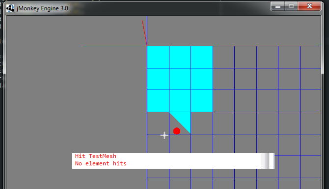
We can also create our own custom meshes on the fly. See the custom mesh tutorial. We have an example of a mesh (see below) that looks like a square with a triangle jutting off, and you can cast a Ray at it to test for hits on the custom mesh. In the picture below, the mesh was clicked once on the triangle that juts out--resulting in the "Hit TestMesh" printout--, and once just outside the triangle--resulting in the "No element hits" output.
We may want to generate custom meshes on the fly for, say, D-shaped elements, or elements with an S shape between two vertices. For instance, if we have a grid of oddly-shaped quads but know their bounding boxes, we could initially filter the hit quads based on their bounding boxes. To determine if the click hits a particular shape, collide a Ray with the remaining mesh(es) to see which ones are hit.

