Notice: This Wiki is now read only and edits are no longer possible. Please see: https://gitlab.eclipse.org/eclipsefdn/helpdesk/-/wikis/Wiki-shutdown-plan for the plan.
EMF Feature Model/Feature Diagram Editor
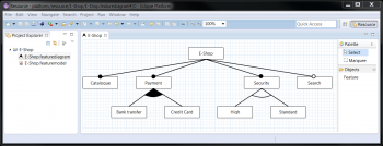
Feature Diagrams are an established, graphical notation for feature models. They use a hierarchical tree structure to present features and their child features as well as their cardinality. One of the most adopted syntax has been established by Czarnecki and Eisenecker [1]
We have developed a Feature Diagram Editor as an Eclipse Plugin based on the EMF Feature Model and the Graphiti framework. This page lists the required resources and provides a guideline how to use the editor.
Contents
Installation
See the overall installation section: EMF_Feature_Model#Installation
Quick Start
There is a new Diagram Wizard. Just choose New -> Other.. -> Feature Diagram to create a new feature model and diagram. The diagram editor will open and one can simply drop new features on the editor canvas or on other features to create a new Child Feature in a new FeatureGroup, or you can drop it on an existing Parent/Child relationship to add the new feature to the existing group.
Changing a Parent-Child-Relationship can simply be done with a right click on the group graphic (the line or the curve) and choose OR/XOR or mandatory/optional from the context menu.
Used Notation
To provide a clear and intuitive notation of the feature diagrams, we have decided for the following conventions:
- FeatureGroups with one child use a single line between Child and Parent and marks the cardinality by the disc notation. In this notation, an filled circle at the end means a mandatory feature and an empty disc an optional one.
- FeatureGroups with more than one child use a polygone presenting a circular arc between the lines of the outer most child features. A filled polygone identifies an OR FeatureGroup and an empty one identifies an XOR (Alternative) FeatureGroup
Mandatory/optional respectively, the XOR/OR characteristics are not explicitly in the meta model but interpreted from the lower and upperbound definitions of the FeatureGroup relationships.
The editor allows to show the cardinalities of those groups. This can be (de-)activate in the context menu by a right click on the diagram stage.
Layout
The feature diagram editor provides a layout algorithm which arranges the features in a hirarchical tree from top to bottom. If a new diagram is generated from an existing featuremodel, this layouting is applied automatically. In addition, it can be triggered manually in the right click context menu by selecting "Layout". However, a manual arrangement is always possible.
Further Features
Expand Collapse
Subtrees of a feature tree can be collapsed and exanded. This can be done either by right clicking the root feature of the sub tree and selecting collapse from the context menue, or by using the mouse over context menu.
Colors
The background and text colors of a feature can be changed by right clicking the feature and selecting either
- Change Text Color
- Change Feature Color
A color picker dialog will be opened to select the color for the selected element.
Legend Box
The diagram editor allows to include a legend box with either all syntax elements or only those included in the current diagram. Again, this is available from the context menu when right-clicking on the diagrams stage and choosing one of
- Show Complete Legend Box
- Show Adapted Legend Box
- Hide Legend Box
Graphical Export
A graphical export is available for pixel graphics (png, gif, bmp, jpg) and vector graphics (svg). This can be done by a right click anywhere on the editor canvas and selecting "Export Diagram..." in the context menu or by pressing "CTRL+O".
Initial Contribution and Credentials
The initial contribution has been developed within the Software Engineering Department of the FZI [2] (Contact: Benjamin Klatt).
Many thanks to Alexander Moor and Zhongwen Jiang, who invested a lot of work and time into this editor.

