Notice: This Wiki is now read only and edits are no longer possible. Please see: https://gitlab.eclipse.org/eclipsefdn/helpdesk/-/wikis/Wiki-shutdown-plan for the plan.
APP4MC/Rover
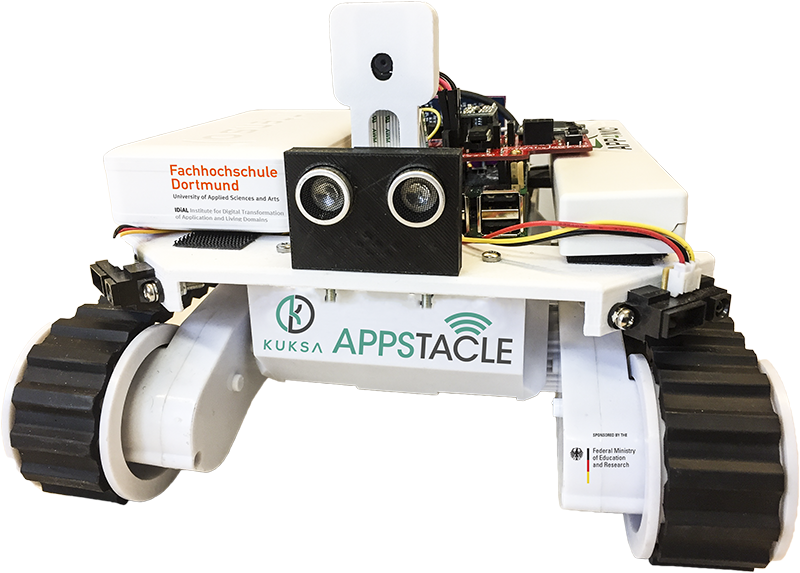
A Rover comprehensive development and documentation is also given at Github with documentation and source repos. The APP4MC Rover is further developed along with the Eclipse Kuksa project.
Contents
APP4MC Rover
Hardware
- Rover kit as described on this page is deprecated, therefore please check the following parts:
| Item | Description | Quantity | Price each in € | Price total | Link exemplarily | Link for Germany |
|---|---|---|---|---|---|---|
| 1 | Rover 5 Robot Chassis (includes 9V 6x AA Battery holder) | 1 | 50 | 50 | Pololu | - |
| 2 | Raspberry Pi 3 with 16GB | 1 | 40 | 40 | Element14 | - |
| 3 | PI Camera | 1 | 25 | 25 | Element14 | - |
| 4 | Sharp GP2Y0A41SK0F Analog Distance Sensor | 4 | 4 | 16 | AE | - |
| 5 | Pololu RPi hat motor controller #2756 | 1 | 35 | 35 | Pololu | - |
| 6 | Motor controller connector | 1 | 1 | 1 | Pololu | - |
| 7 | Powerbank for RPI | 1 | 25 | 25 | Element14 or GB | Conrad |
| 8 | Rover-Sense-Layer | 1 | ~14 | ~14 | Via KiCAD e.g. PCBWay or AllPCB using the provided files | - |
| 9 | A/D Converter | 1 | 3,15 | 3,15 | AE | Conrad |
| 10 | Logic Level Converters | 2 | 1,06 | 2,12 | AE (size has to be checked!) | Link |
| 11 | Magnetometer | 1 | 1,58 | 1,58 | AE | - |
| 12 | US sensor SR04 | 2 | 2 | 4 | AE | - |
| 13 | Temp. / Hum. sensor | 1 | 2,22 | 2,22 | AE | Amazon |
| 14 | OLED Display | 1 | 3 | 3 | AE | Amazon |
| 15 | Accelerometer / Gyro | 1 | 0,94 | 0,94 | AE | Sertronics |
| 16 | Buzzer | 1 | 1,5 | 1,5 (10 pcs) | AE | Conrad |
| 17 | Resistors | 3 | x | 1 (100 pcs) | AE | Conrad |
| 18 | Buttons | 2 | x | 1 (50 pcs) | AE | Conrad |
| 19 | Pin Header | 1 | 1 | 1 (10 pcs) | AE | Conrad |
| 20 | Spacers | 6 | 0,05 | 0,30 | AE | - |
| 21 | IC Socket | 1 | 1 | 0,18 | - | Conrad |
| 22 | Pin Heads straight 1x36 | 2 | 1,92 | 3,84 | - | Conrad |
| 23 | Pin Heads angle1x36 | 1 | 2,6 | 2,6 | - | Conrad |
| 24 | Distance bolts | 2 | 0,23 | 0,46 | - | Sertronics |
| 25 | Voltage Converter | 1 | 1,77 | 1,77 | AE | - |
| ∑ | 37 | - | ~240 EUR | No shipping, assembly included | - |
3D Prints
3D extensions, to be printed via a 3D printer, are provided >>> here <<< for attaching (a) 4 IR sensors, (b) 2 US sensors, and (c) the RPI camera. Future versions may include a battery and RPI3 holder in order to provide a more stable setup. Feel free to help us with that :-)
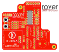
RoverSenseLayer
Repo with KiCAD files: GitHub
Software
- the Rover's documentation (install guide, web-access incl. camera stream, and tracing possibilities), the AMALTHEA model, and the application SW can be found @: git Rover repository
- Rover SD card images are available here
Investigation results
- All ultra sonic sensors (Grove, SRF02, and SR04) give relatively unreliable values
- The compass values highly depend on its location circumstances - you may encounter unreliable values here as well
Since we do not focus the Rover's applications itself, we leave any implementations for sophisticated front and rear distance- or cardinal direction- measurements via additional or different sensors or any filtering algorithms to the community
Included Implementations
- Displaying Hono, BT, and Wifi connection via OLED display
- Website generation for live stream, controls, and sensor data / CPU utilisation visualisation
- Wifi hotspot
- ACC
- Grove / SR04 / SRF02 US Sensor access via wiringPi library but unreliable values
- IR sensor access
- Hono interaction
- Buzzer implementation
Upcoming Implementations
- Bluetooth implementation to allow Android App control
- Temp. Hum. sensor, Accelerometer, Gyro
Assembling the APP4MC Rover (DRAFT!)
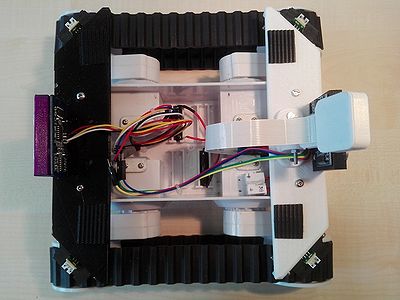
Since the rover is a platform for testing soft- and hardware, it is still under construction. For this reason, some parts are only loosely mounted. If desired some parts can be glued for a tighter hold. You also can use Velcro. An additional source in the Rover hardware can be found in the rover-docs.
Chassis
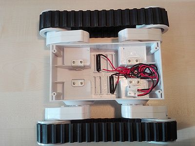
All parts of the rover are placed inside or onto the Rover 5 tracked chassis. Parts:
- Rover 5 tracked chassis (without encoders) Manual
- 3D printed front and rear mount platform Files
- 3D printed Camera housing Files Stand, Files Housing
- 2x 3D Printed Ultrasonic sensor housing Files
- Sensors
- 4x SHARP Infrared distance sensor
- 2x Ultrasonic distance sensor
- 1x Camera
- Power circuit
- 1x power bank (with USB out, 5V/2.4A) + StepUp Voltage Converter set to 9V for the motors
- Circuit breaker
- 19x M.3 screws
- 15x M.3 nuts
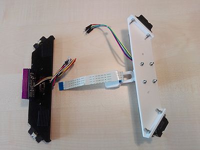
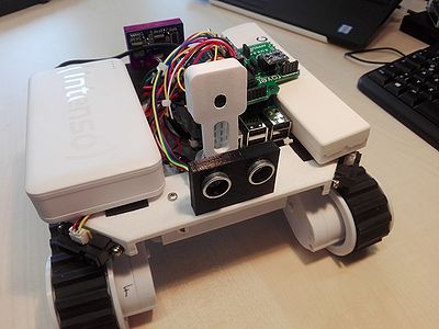
Mount the Infrared and Ultrasonic sensors on the 3D printed front and rear platforms. Also mount the Camera onto the front platform. Use M.3 screws and nuts for that. For a better visual feedback on where the front and back is, both platforms were printed in different colors (white = front).
Place both platforms onto the chassis and tighten them with M.3 screws directly to the chassis. Since the forward and backward speed are identical, you have to decide which side will be the front. In this case we decided for the side on which the motors are placed.
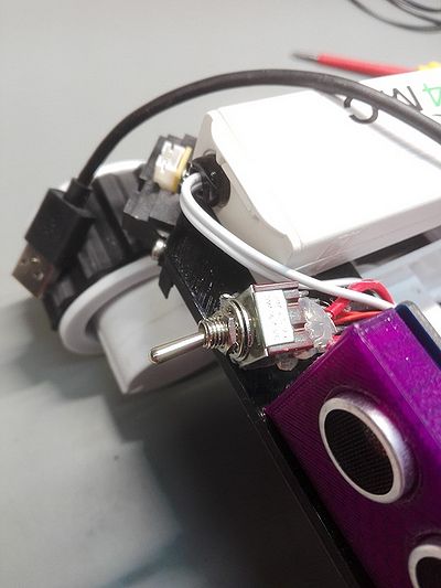
Optional: A circuit breaker can be added to the cables which power the Raspberry Pi and the motors. Therefore, the outputs are directly soldered to the breaker. Here, the breaker is placed in the USB cable towards the Pi (shown in the plan).
Intelligence-Stack
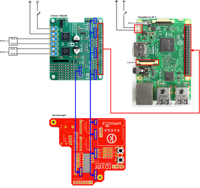
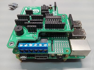
The intelligence-stack includes the RaspberryPi3, the motor shield, and the Sense-Layer. The three boards are connected on top of each other i.e.: 1. Sense-Layer (Top) 2. Motor Shield (Middle) 3. Raspberry PI3 (Bottom)
Parts:
- Raspberry Pi 3
- Motor Shield (Schematics)
- Rover Sense-Layer
- Temperature Sensor
- Display
- Logic Level Shifter
- A/D Converter
- Buzzer
- Buttons (shutdown, user defined)
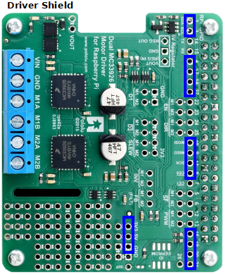
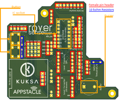
Assemble and solder (if not already done) all parts onto the Driver Shield and Rover Sense-Layer. For the Driver Shield follow the instructions that are shipped with it. You may need to solder additional male pin headers onto the shield (blue areas).
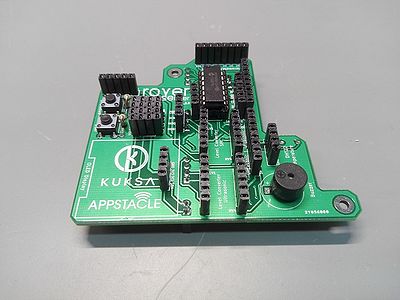
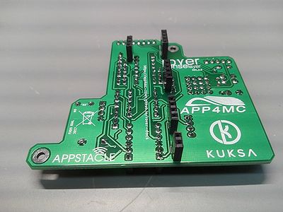
Solder all parts (from this list) onto the Sense-Layer. A soldering mask is printed on the board. The finished board should look like this:
Put all three boards together (Raspberry Pi 3 <- Driver Shield <- Rover Sense-Layer). You may use spacers between the boards. The height depends on your pin heads. We use 10 mm spacers or none, as we often disassemble the stack.
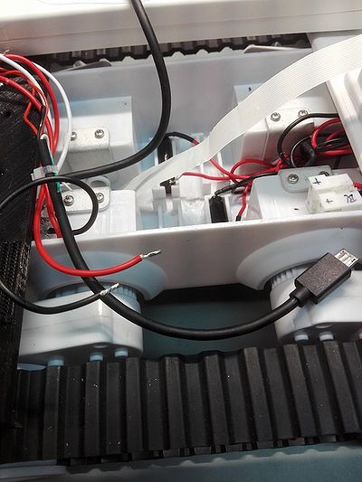
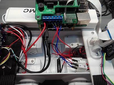
The Intelligence-Stack is loosely placed in the chassis. The power and motor cables are connected as shown in the quick wire guide. Do not forget to connect the camera as it may be difficult to reach the socket on the Pi later:
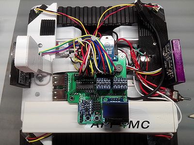
Connect all other sensors (Infrared, Ultrasonic, Temperature, …) as well as the logic-level-shifters, A/D converter and the display to the Sense-Layer:
After adding the power bank and the voltage converter (set to 9V) and connecting the motors, and batteries the Rover is ready to go.
Flash your SD-card with the latest Kuksa-AGL-Image available at Repo Dortmund or build your own Kuksa-AGL image and start Hacking(thumbs up).
Outlook
UMTS/LTE connection
The Rover's wifi can be set up as an access point for a local setup, e.g. to use the Rover_Web_UI, or as a wifi client to connect to an existing network, e.g. to use the Rover_Telemetry_UI and exchange data with a cloud instance. For external communication a UMTS/LTE module should be used in the future. For lab setups it is also sufficient to use an additional Wi-Fi stick or the RJ45 connection on the Pi, to mock that connection.

