Notice: this Wiki will be going read only early in 2024 and edits will no longer be possible. Please see: https://gitlab.eclipse.org/eclipsefdn/helpdesk/-/wikis/Wiki-shutdown-plan for the plan.
Papyrus/customizations/manufacturing/aas/bom
Contents
Graphical modeling editors
AAS diagram
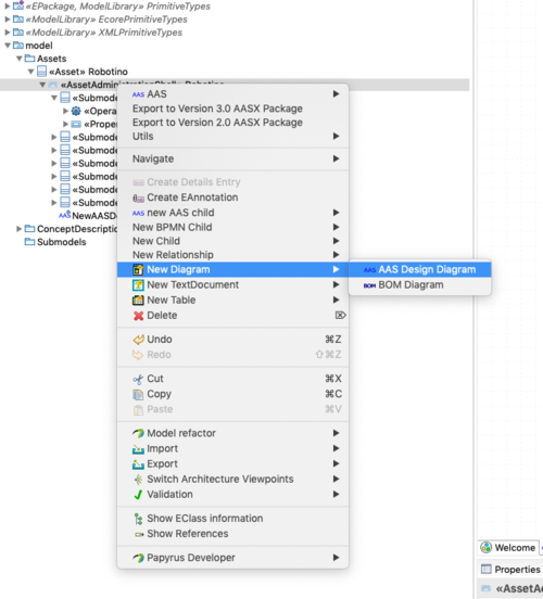
To create new AAS Diagram rigth click on the model explorer -> New Diagram -> AAS Design Diagram.
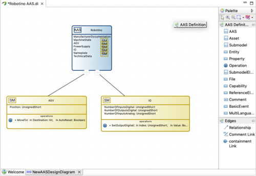
AAS diagram are used to create new AAS models, Submodel and other elements shown in the palette of the figure below.
Bill of material composition diagram (BOM)
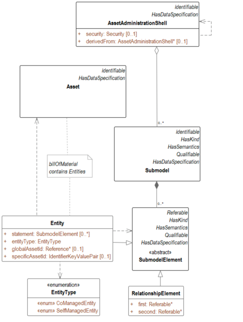
Bill of Material diagrams enable the description of the internal structure of an asset. A bill of material is concretely a submodel inside the AAS that contains only entities. Each entity is referencing a specific asset as shown in the AAS meta model extract.
Bill of material composition (BOM) is a container of sub-component.
It is possible to create a BOM diagram for the BOM Submodel of the composite AAS.
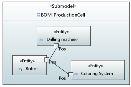
For example, the BOM diagram of the production cell contains three entities, the robot, the drilling machine and the coloring system.
These entities are related with each other by the common property "Pos" (for position).
Process diagram
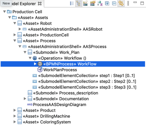
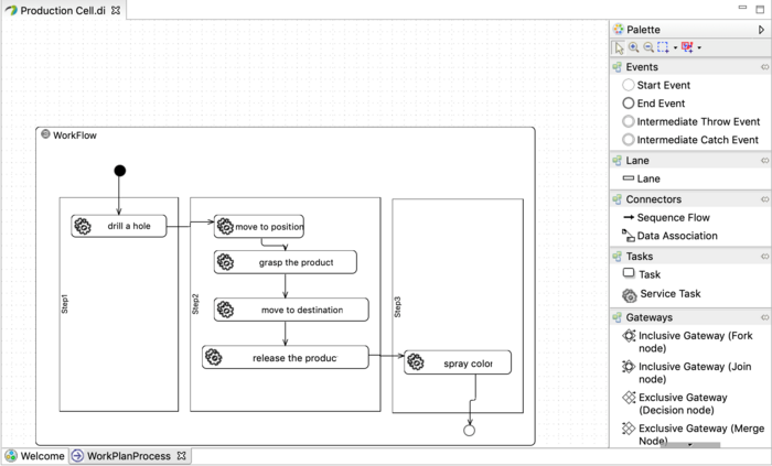
The production process can also be represented in an Asset Administration Shell with a submodel “Work Plan” where we can define the process steps and requirements. We choose to attach the process model to the submodel element “operation” as shown in the Figure below. From this submodel element a BPMN Process diagram can be created to describe the tasks and possibly execute them.
This process diagram is a customized UML activity diagram composed of a subset of the BPMN standard concepts which are visible in the palette.

