Notice: this Wiki will be going read only early in 2024 and edits will no longer be possible. Please see: https://gitlab.eclipse.org/eclipsefdn/helpdesk/-/wikis/Wiki-shutdown-plan for the plan.
GEMS Metamodeling Tutorial
Contents
- 1 Tutorial Overview
- 2 Tutorial Example Modeling Application
- 3 Creating a Java Project for the Modeling Tool
- 4 Creating the GEMS Metamodel
- 5 Setting up the Workspace and Views
- 6 Defining the Deployment Metamodel Properties
- 7 An Overview of the GEMS Palette
- 8 Defining the Deployment Metamodel
- 9 Generating the Plugin for the Modeling Tool
- 10 Overview of the Generated Code
- 11 Running the Generated Modeling Tool
- 12 The Complete Modeling Tool
- 13 Changing the Look of the Modeling Tool
Tutorial Overview
This tutorial presents the basics of creating a metamodel using GEMS and generating an Eclipse plugin for editing instances of the language defined by the metamodel. The tutorial allows you to create an Eclipse Graphical Editor Framework (GEF) based modeling tool without any Java coding or XML editing.
Tutorial Example Modeling Application
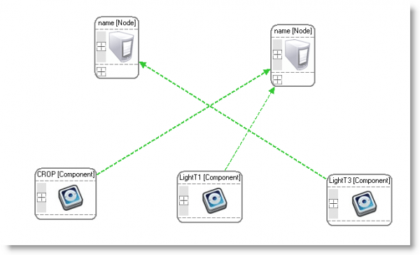
The example application that we will create in this tutorial is a modeling tool for specifying the deployment of software components to nodes (servers) in a datacenter. We will create a simple modeling tool that provides elements that can be dropped from the palette into the model to specify: 1) software components, 2) hardware nodes, 3) properties of hardware nodes, and 4) properties of components. You can skip to the end of this tutorial and take a look at the screenshot of the final tool to see where we are going.
Creating a Java Project for the Modeling Tool
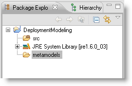
The first thing we need to do to create our new modeling tool is to create a Java project to hold the code for it. From the file menu, create a new Java Project and ensure that "Create separate folders for sources and class files" is checked. After creating the project, create a new folder (not a source folder) and name it "metamodels".
Creating the GEMS Metamodel
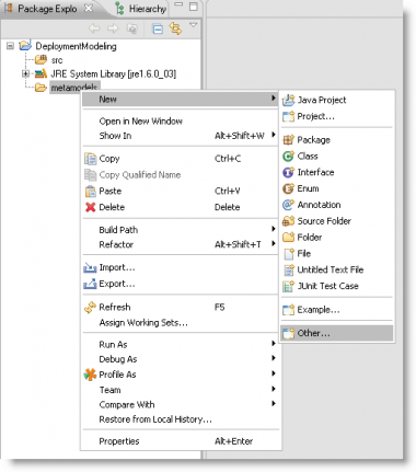
Next, we need to create a new GEMS2 Metamodel to add to the project. Right-click on the "metamodels" folder and select "Other".
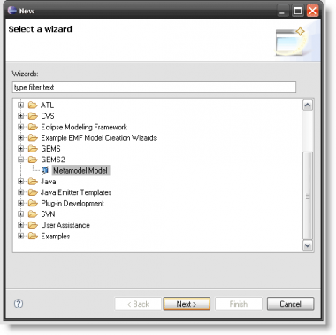
When the new file type selector appears, expand the "GEMS2" folder and select "Metamodel model". Click "Next" and then name your model "deployment.gemsmeta2". Make sure that the "metamodels" folder is selected as the parent folder and then click "Finish".
Setting up the Workspace and Views
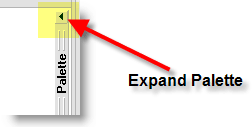
After creating the new Metamodel model, the model should immediately be opened in a new editor. First, expand the modeling palette if it is closed. The palette is expanded by clicking on the small expansion icon in the upper right hand corner of the editor.
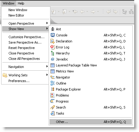
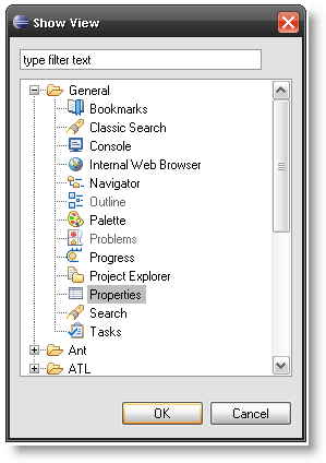
Next, make sure that the properties view is open. To open the properties view, from the "Window" menu, select "Show View" and then select "Other". When the view selection window appears, expand the "General" folder, select "Properties", and click "OK".
Defining the Deployment Metamodel Properties
Now that the properties view is open, we can set some of the basic properties of the metamodel. Left-click inside the blank modeling canvas. The properties for the metamodel should appear in the properties view. Set the properties:
- Category = "Deployment"
- DSMLID = "http://www.sf.net/projects/gems/dsml/deployment"
- FileExtensions = "dmod"
- Name = "Deployment"
These properties that we have just defined will determine a number of ways that your modeling tool integrates with Eclipse. First, the "Category" will be the name of the folder that your modeling tool's models show up under in the new file wizard (e.g. GEMS Metamodels show up under the "GEMS2" category). The "DSMLID" that you specified will be a namespace used to identify your modeling language. It is very important that all modeling languages in a single Eclipse installation have different DSMLIDs. The "FileExtensions" determines the file extension that your models will have. All files with this extension will automatically be associated with your modeling tool's editor. Finally, the "Name" will determine the name for your models as it will be shown underneath its folder in the new file wizard. Your name must NOT contain any spaces and must start with a letter (preferably a capital letter).
An Overview of the GEMS Palette
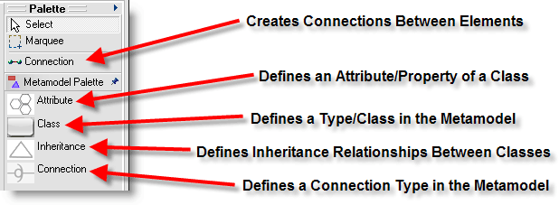
The metamodel palette contains a number of tools that are used to edit your metamodel. An overview of the tools:
General Tools
- "Select" allows you to click on elements to make selections in the model.
- "Marquee" allows you to draw a box to define a selection.
- "Connection" allows you to draw a line between two elements. Please note the difference between it and the "Connection" element of the metamodel that is described below.
Metamodel Palette
- "Class" defines a new type in your modeling language. Click on Class and then again on the canvas to add a new Class element to the metamodel. Each Class defined in your metamodel will show up (although this can be customized) as an element on the palette in your generated modeling tool. Classes can have "Attributes" added to them that can be edited in the properties view of the generated modeling tool.
- "Attribute" defines a property of a "Class" or "Connection" that will be visible and editable in the properties pane of the generated modeling tool. Click on the Attribute palette entry and then click again on either a Class or Connection element in the model to add a new Attribute to it.
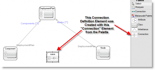
- "Connection" defines a new type of line that can be drawn between two model elements in the generated modeling tool. The Connection is very similar to a UML "Association Class". The Connection element on the Metamodel Palette differs from the Connection tool in that it is used to define lines that can be drawn between elements in the generated modeling tool. The Connection tool that is not on the Metamodel Palette drawer is used to draw connections (lines) between elements in the metamodel. The distinction will make more sense after completing this tutorial.
Defining the Deployment Metamodel
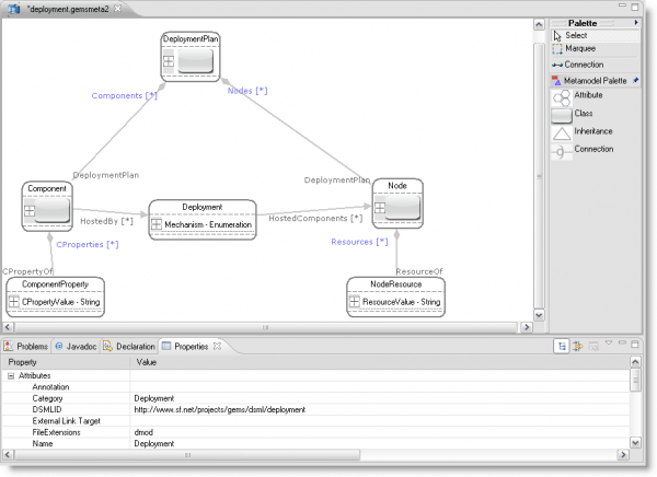
Now that we have set the basic properties of our Metamodel, we can begin defining the elements in our modeling language. First, we are going to create a root element that will contain all other elements in our modeling language. This root element will be called a "Deployment Plan".
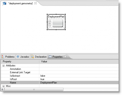
- Add a new Class to the metamodel by clicking on the Class palette entry and then clicking again on the modeling canvas
- Click on the newly create Class to select it
- In the properties view, change the "Name" of the Class to "DeploymentPlan" and the "IsRoot" attribute to "true"
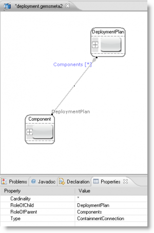
Next, we are going to add another Class to our metamodel to represent the software components that will be specifying how to deploy in the datacenter. Add a new Class to the metamodel and name it "Component". Now, we need to specify that the Component Class is contained by the DeploymentPlan:
- Select the Connection Tool (not the Connection element) that is above the "Metamodel Palette" drawer
- Click on the new Component Class, this should initiate the drawing of a new line
- Click again on the DeploymentPlan Class to terminate the connection
- Select the newly drawn line between Component and DeploymentPlan
- In the properties pane, set "RoleOfParent" to "Components" and "RoleOfChild" to "DeploymentPlan"
Now, we will add another Class to represent our hardware nodes or servers in the deployment models. Add a new Class to the Metamodel and name it "Node". Create a Containment relationship from Node to DeploymentPlan (just like you did for Component) and set the "RoleOfParent" to "Nodes" and the "RoleOfChild" to "DeploymentPlan".
In our deployment modeling tool, we want to be able to draw a line from a Component instance to a Node instance that it should be deployed to. To define this Connection (line) that can be created between the two types, we add a Connection element to the model. This Connection element is created by the Connection entry on the Metamodel Palette drawer, which is the Connection entry on the bottom. To define the Connection:
- Click the Connection element entry
- Click again on the canvas to add it to the metamodel
- Click the new Connection element to select it
- In the properties pane, change its name to "Deployment"
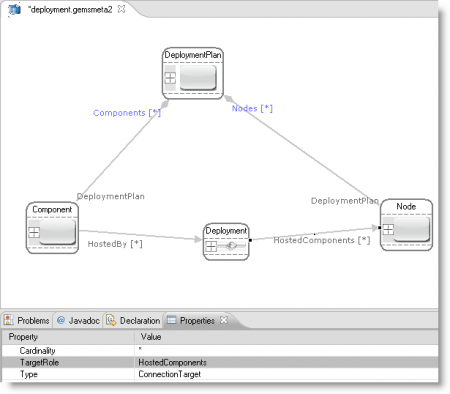
- Select the Connection Tool on the palette (the top most Connection entry)
- Click on Component to start a connection
- Click again on the Deployment Connection entity
- Select the newly created line and change its SourceRole to "HostedBy"
- Select the Connection Tool
- Click on the Deployment Connection to start a new connection
- Click on the Node to end the connection
- Select the newly created line and change its "TargetRole" to "HostedComponents"
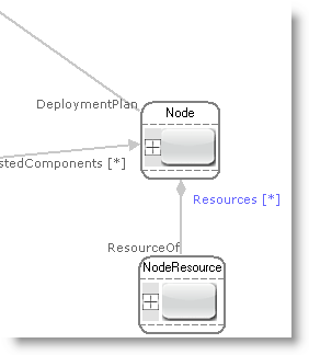
Now, we would like to be able to capture the resources, such as RAM, available on each Node. To do this, we are going to add a new "NodeResource" class that is contained by Node. Add a new Class to the Metamodel, name it "NodeResource", and create a Containment relationship from it to Node. Set "RoleOfChild" to "ResourceOf" and "RoleOfParent" to "Resources".
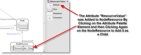
We can add an Attribute to NodeResource to capture the value of the resource. For example, a RAM NodeResource might have a value of 1024. To add the Attribute to NodeResouce:
- Select the Attribute entry on the palette
- Click on the NodeResource Class to add the Attribute to it
- Select the new Attribute
- Name the Attribute "ResourceValue"
- Set the "AttributeType" to "String"
- Set the "DefaultValue" to "0"
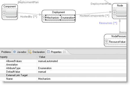
To provide more information about how a Component is deployed to a Node, we are going to add an Attribute to the Deployment Connection. The new Attribute will be called "Mechanism" and will determine if the Component is manually deployed or deployed through some automated means. To add the "Mechanism" Attribute:
- Select the Attribute entry on the palette
- Click on the Deployment Connection to add the Attribute to it
- Select the new Attribute
- Name the Attribute "Mechanism"
- Set the "AttributeType" to "Enumeration"
- Set the "AllowedValues" to "manual,automated"
- Set the "DefaultValue" to "manual"
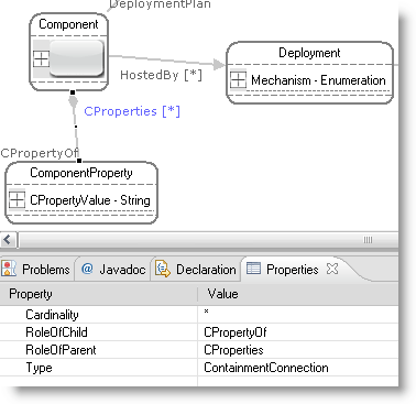
Finally, we want to add another Class to capture the properties of a software component, such as the total number of licenses for it. To do this, we can add another Class and name it "ComponentProperty". Create a containment relationship from ComponentProperty to Componenent with "RoleOfChild" set to "CPropertyOf" and "RoleOfParent" set to "CProperties". Add an Attribute to ComponentProperty and name it "CPropertyValue". Set the "AttributeType" to "String" and the "DefaultValue" to "0".
The complete metamodel is shown below:
Generating the Plugin for the Modeling Tool
With a completed Metamodel, we can use GEMS to generate the Java, Eclipse Plugin Descriptors, and other code needed to implement a modeling tool for our modeling language. To generate the code for the modeling tool:
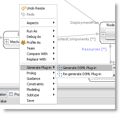
- Right-click on the modeling canvas, "Generate Plug-in", "Generate DSML Plug-in"
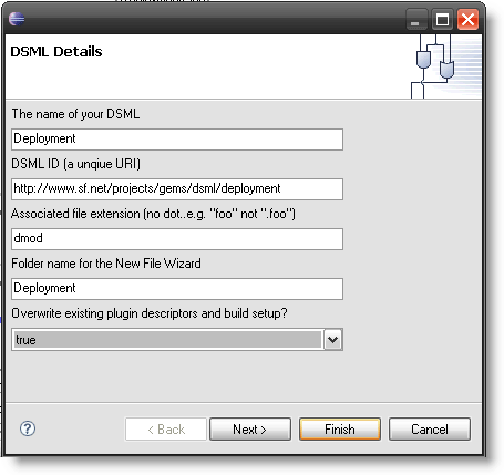
- Change "Overwrite existing plugin descriptors and build setup?" to true
- Next
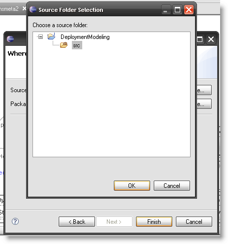
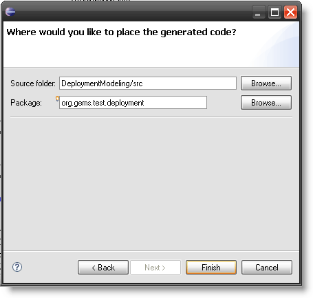
- Click the "Browse" button next to "Source Folder"
- Use the file navigator to select the "src" source folder of your modeling tool's Java project and select "OK"
- In the "Package" field, type "org.gems.test.deployment", this is the Java package that your code will be generated into and the ID that will be assigned to your Eclpise plug-in
- Click "Finish" and wait for GEMS to generate your modeling tool
Overview of the Generated Code
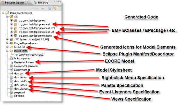
GEMS generates a number of code artifacts from your metamodel. These artifacts from the implementation of the modeling tool:
- GEMS classes in the package org.gems.test.deployment
- Icons for your modeling elements in org.gems.test.deployment.icons (these can be overwritten with your own custom icons)
- EMF classes (EClasses), an EPackage, etc. in org.gems.test.emf.*
- A plugin descriptor and manifest in Manifest/Manifest.MF and plugin.xml
- A build setup for your plug-in in build.properties
- A classpath setup for your project
- A stylesheet (dsml.css) for your modeling tool that can be changed to adjust the look and feel
- A palette specification (dsml.palette) that can be modified to change the palette of your generated modeling tool
- A file (dsml.triggers) where event listeners can be registered to watch for and respond to changes in your models
- A definition of the views (dsml.viewdef) that are available in your modeling tool
- A README file that explains how to get started with the various generated artifacts
Running the Generated Modeling Tool
To run the tool, we can launch a new Eclipse runtime workbench with the plug-in code loaded inside. To launch a runtime workbench:
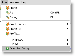
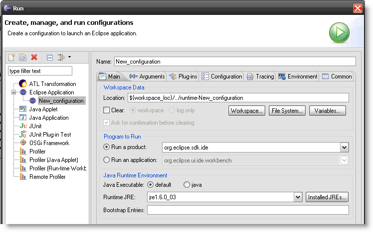
- From the "Run" menu, choose "Open Run Dialog"
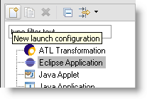
- Select "Eclipse Application" and click the "New Launch Configuration" button
- Select the newly created launch configuration, click the "Plug-ins" tab and ensure that "Launch with" is set to "all workspace and enabled target plug-ins"
- Click Run to launch the runtime workbench
Once the runtime workbench launches, we can create a new instance of our deployment modeling language:
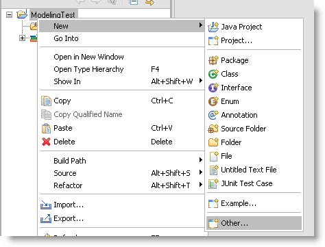
- After the new runtime workbench launches, create a new Java project and then right-click, "New", "Other"
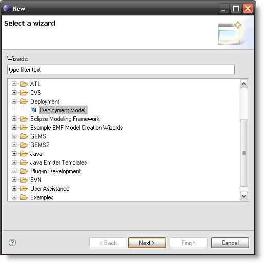
- Find the category you assigned to your modeling language (Deployment), expand it, and select and create a new instance of your modeling language (Deployment Model)
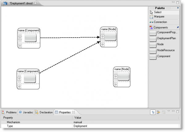
The Complete Modeling Tool
The completed modeling tool without any stylesheet and icon adjustments:
Changing the Look of the Modeling Tool
The next tutorial in this series presents the GEMS stylesheet language that can be used to change the look and feel: GEMS Stylesheet Tutorial
The completed modeling tool with stylesheet and icon adjustments:
