Notice: this Wiki will be going read only early in 2024 and edits will no longer be possible. Please see: https://gitlab.eclipse.org/eclipsefdn/helpdesk/-/wikis/Wiki-shutdown-plan for the plan.
Difference between revisions of "Papyrus/customizations/robotics/ros2"
(→ROS2 code generation) |
(→ROS2 code generation) |
||
| Line 64: | Line 64: | ||
</center> | </center> | ||
| − | The following | + | The following text-box outlines the structure of the generated artefacts for a message package: |
folder (corresponds to a message package, i.e. a sub-packages within a RobMoSys service definition module) | folder (corresponds to a message package, i.e. a sub-packages within a RobMoSys service definition module) | ||
CMakeLists.txt - Makefile | CMakeLists.txt - Makefile | ||
| Line 96: | Line 96: | ||
The ROS2 demos contain examples that establish the connection between two nodes by using the same topic name. While this is fine for an example, a component must not "know" to which component it will be connected in a system. This assures its re-usability on source and binary level. The code generator uses the port names as topics. Topic re-mapping (see below) enables the connection on the system level. | The ROS2 demos contain examples that establish the connection between two nodes by using the same topic name. While this is fine for an example, a component must not "know" to which component it will be connected in a system. This assures its re-usability on source and binary level. The code generator uses the port names as topics. Topic re-mapping (see below) enables the connection on the system level. | ||
| − | + | ||
| + | The following text-box outlines the structure of the generated artefacts for a component definition: | ||
| + | folder (corresponds to RobMoSys component-definition-module) | ||
| + | src-gen - generated source and include files | ||
| + | CMakeLists.txt - Makefile | ||
| + | package.xml - Meta-data/build info | ||
| + | |||
=== System code generation === | === System code generation === | ||
| Line 108: | Line 114: | ||
The script below shows the generated launch file for the dummy_robot system | The script below shows the generated launch file for the dummy_robot system | ||
| − | + | def generate_launch_description(): | |
| − | def generate_launch_description(): | + | ld = launch.LaunchDescription() |
| − | + | ld.add_entity(LifecycleNode( | |
| − | + | node_name='ComponentInstance1', | |
| − | + | package='dummy_joint_statescompdef', node_executable='Dummy_joint_states', | |
| − | + | remappings=[ | |
| − | + | ('joint_states', 'ComponentInstance1/JointState/joint_states') | |
| − | + | ], | |
| − | + | parameters=['cfg/param.yaml'] | |
| − | + | )) | |
| − | + | ... idem for Dummy_laser, Dummy_map_server, Robot_state_publisher and rviz | |
| − | + | ||
| − | + | The following text-box outlines the structure of the generated artefacts for a component definition: | |
| + | |||
| + | folder (this corresponds RobMoSys system-component-architecture) | ||
| + | launch.py | ||
| + | cfg - subfolder for parameters | ||
| + | params.yaml - generated parameter file containing the (non-default) parameter values defined at system-level | ||
== ROS2 reverse == | == ROS2 reverse == | ||
Revision as of 11:20, 13 December 2019
Contents
ROS2
Acknowledgements
The work on Papyrus for Robotics in general is supported by the RobMoSys project. The ROS2 support is supported by the project ROSIN FTP (focused-technical project) ROS MDD
Mapping RobMoSys concepts to ROS2
Communication patterns
One of the primary issues in mapping RobMoSys concepts to ROS2 is how to map RobMoSys interaction patterns to ROS2 . In the sequel, we outline this for each [communication pattern] in RobMoSys.
QUERY pattern
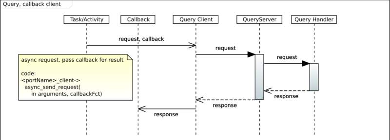
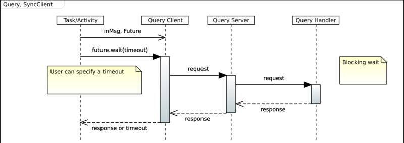
The QUERY pattern is a classical client/server pattern with one server and n clients. The clients execute a request and expect a response. There are two ways, how a client can handle responses: either with a blocking wait or by receiving a callback with the response (this option primarily affects the activity definition within a component). Both options are supported by ROS2 services. On the server side, a service request is executed within a handler. In case of ROS2, requests are always executed by a ROS2 multi-threaded executor that calls the request handler.
SEND pattern
The SEND pattern in RobMoSys is an asynchronous service request without expecting a response. While it seems conceptually close to service requests, it cannot be mapped to ROS2 services that always require a response (while either request or response may be empty, a server always has to send a response, even if empty).
PUSH pattern
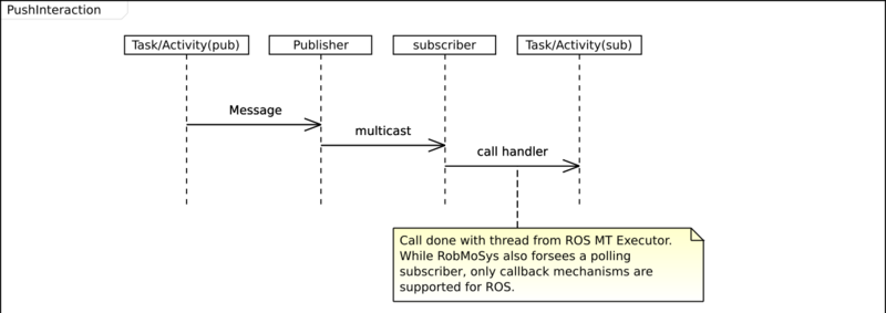
The PUSH pattern in RobMoSys is an asynchronous message publication with one publisher and n subscribers. This is directly mapped to ROS2 publish/subscribe with messages. A publisher can directly push messages without queuing to subscribed consumers.
EVENT pattern
The EVENT patterns enables asynchronous, filtered event handling. It is currently not supported by the ROS2 mapping.
Component lifecycle
As RobMoSys component have a lifecycle (see RobMoSys wiki, a RobMoSys component is mapped to a ROS2 lifecycle node. By default, a component cycles from an initial state to a configured and then to an activate state. Periodic tasks are started when the component enters the activate state.
ROS2 code generation
Message package generation
A RobMoSys ServiceDefinition model is mapped a set of ROS2 packages containing messages and services. As for the other code generation artifacts, a message package will be generated in its own Eclipse CDT project. This CDT project is configured to use colcon as build command, options can be configured in the preferences (type "ROS2" in the filter to see the associated preference page).
It is only necessary to create a new ROS2 message/service package, if that does not already exist. Service generation is not invoked directly from a service definition model, but will be invoked automatically during component generation, if that component references non standard messages or services. The generator uses a preference dialog below (see below) in order to detemine what a standard message is.
The following text-box outlines the structure of the generated artefacts for a message package:
 folder (corresponds to a message package, i.e. a sub-packages within a RobMoSys service definition module)
   CMakeLists.txt - Makefile
   package.xml - Meta-data/build info
   msg - folder with message definitions
   srv - folder with service definitions
Component code generation
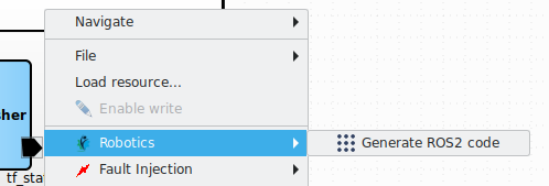
Papyrus for robotics supports the generation of (C++) code for ROS2. The code generation can be triggered via the "Robotics" context menu when a component definition or a system (component assembly) is selected.
Let's look at an example, the dummy_joint_states component that is part of the standard ROS2 demos. The following figure shows the RobMoSys view of this component. As the source code creates a publisher with the topic "joint_states" and the message type "JointState", the RobMoSys model of this components contains a provided PUSH port with the respective name and type.
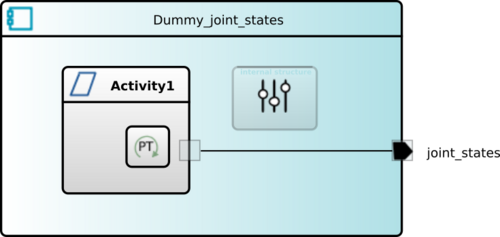
dummy_joint_states component, modeled with Papyrus for Robotics
The original source code performs an initialization of a message and then enters a loop. In this loop, it modifies an entry of the message and performs a wait. The mapping to RobMoSys implies splitting this code into two parts, the initialization of the message and the periodic publication of the modified message. The result is an Activity with two functions that take over the respective part. The period length is modeled via a periodic timer.
Compared to the monolithic source code that contained the creation of a publisher port, the initialization of a message and then a periodic loop with a hard-coded period, the corresponding model separates these aspects into a modeled port and two reusable (composable) functions.
If a component is selected, a ROS2 package can be generated for this component, as shown in the following dialog.
Currently, each RobMoSys component is mapped to a dedicated ROS2 package containing the code for a node. The generated package contains generated build files (package.xml and CMakeLists.txt), as well as a src-gen folder with the C++ code that instantiates a ROS2 node when executed. On the RobMoSys level, the behavior of a component is described by activities which in turn are broken down into functions. The code of these functions can be embedded into the model and will be copied into the generated code.
The ROS2 demos contain examples that establish the connection between two nodes by using the same topic name. While this is fine for an example, a component must not "know" to which component it will be connected in a system. This assures its re-usability on source and binary level. The code generator uses the port names as topics. Topic re-mapping (see below) enables the connection on the system level.
The following text-box outlines the structure of the generated artefacts for a component definition:
 folder (corresponds to RobMoSys component-definition-module)
   src-gen - generated source and include files
   CMakeLists.txt - Makefile
   package.xml - Meta-data/build info
System code generation
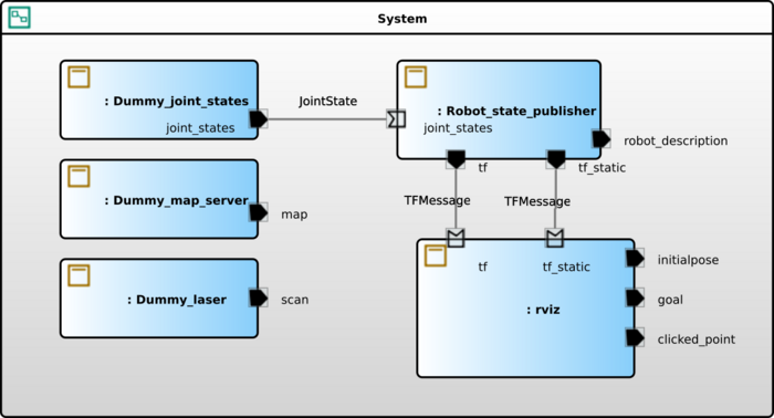
If a system is selected, code is generated for all components within the system. In addition, a python launch script that brings-up the robotic system is generated. It references a yaml file that contains port/topic remappings and references a yaml file taking into account parameter values that override the default ones for the component. The topic remappings establish the connection between the component instances (see topics above).
The script below shows the generated launch file for the dummy_robot system
 def generate_launch_description():
   ld = launch.LaunchDescription()
   ld.add_entity(LifecycleNode(
     node_name='ComponentInstance1',
     package='dummy_joint_statescompdef', node_executable='Dummy_joint_states',
     remappings=[
       ('joint_states', 'ComponentInstance1/JointState/joint_states')
     ],
     parameters=['cfg/param.yaml']
   ))
   ... idem for Dummy_laser, Dummy_map_server, Robot_state_publisher and rviz
The following text-box outlines the structure of the generated artefacts for a component definition:
 folder (this corresponds RobMoSys system-component-architecture)
   launch.py
   cfg - subfolder for parameters
      params.yaml - generated parameter file containing the (non-default) parameter values defined at system-level
ROS2 reverse
In order to start creating ROS2 compatible components with Papyrus for Robotics, it is important to enable referencing standard ROS2 messages. These have been made available in a model library in form of RobMoSys compliant communication objects and service definitions. This library has been obtained by a reverse functionality within Papyrus for robotics that scans the available list of ros messages and services. If the message is not already existing, it will be created.
It is also possible to create a set of component definitions from the currently running ROS nodes. This reverse mechanism is currently limited to the structural part of a component, i.e. its ports along with the provided or required service definitions.
The following screenshots shows the context menus for starting reverse engineering.

