Notice: this Wiki will be going read only early in 2024 and edits will no longer be possible. Please see: https://gitlab.eclipse.org/eclipsefdn/helpdesk/-/wikis/Wiki-shutdown-plan for the plan.
OM2M/one/IPE Sample
| OM2M | |
| Website | |
| Download | |
| Community | |
| Mailing List • Forums • IRC • mattermost | |
| Issues | |
| Open • Help Wanted • Bug Day | |
| Contribute | |
| Browse Source |
This page describe the IPE Sample and good practices for designing and building and IPE.
Contents
Why an IPE?
The aim of an Interworking Proxy Entity is to create an interface from a device technology / specific network to the oneM2M standard. In our distribution, we provide an IPE sample as an example of what can be done. In this instance, we only have simulated lamps (using Java Swing) to show the behaviour of that kind of program.
In OM2M, an IPE can be embedded in the platform by making it a plugin. As we use the OSGi framework, you will be able to deploy your plugin on your running instance and manage the state of your plugin (start and stop).
Architecture of an IPE
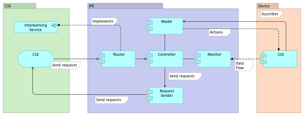
The provided sample IPE has a complex architecture to show how you can design and build your own plugin. The following schema sum up this architecture:
On the left side of the schema, we can see the CSE component where we will be able to send request. On the right side, we have the set of devices we want to integrate to our system.
Controller package
In this package we will find two components:
- Life cycle manager
This component is in charge of starting and stopping internal components, handle the creation of resource in the CSE at the start of the plugin and so on. Also, it has to stop any working thread in the case that the stop method of the Activator has been called.
- Sample Controller
The aim of the controller component is to make the interaction between the devices following the orders coming from the oneM2M interface. As your plugin will receive requests, the controller will perform the corresponding operation on the devices (retrieve the state, switch on a lamp, etc.).
Monitor component
The monitor component has to retrieve information depending on the specific technology and push that information into the CSE. For instance, it can have a thread that will look for a sensor value periodically.
Model package
As we have simulated lamps, we have to represent them using Java objects to store their "real values". This represents the devices we are going to monitor and control.
GUI component
This component only shows the state of the lamps and allows us to interact with it.
Other classes
The activator, as described in the Add you plugin tutorial, is the entry point for OSGi plugins.
The Sample Router class implements the InterworkingService interface and will be the entry point for requests that target your IPE. It will send the request to the corresponding method of the controller.
The ObixUtil is here to create oBIX representation(s?) for the devices.
The request sender is a utility class that will create oneM2M requests to send to the CSE using java objects. You can get inspiration from those requests to build your own for your application.


