Notice: this Wiki will be going read only early in 2024 and edits will no longer be possible. Please see: https://gitlab.eclipse.org/eclipsefdn/helpdesk/-/wikis/Wiki-shutdown-plan for the plan.
BPMN2-Modeler/DeveloperTutorials/ToolPaletteFragments
Tool Palette Fragments
The BPMN2 Modeler's Tool Palette is extremely flexible and can be extended with user-defined "snippets" or compound tool items. The "Workflow Patterns" Tool Drawer is an example of this type of extension. Please use the Core Extension Points document as a reference.
In this tutorial we will be using the BPMN2 Modeler's ".bpmn2config" configuration folder to define some BPMN2 snippets for the Tool Palette, simply because this will be an iterative process and changing some XML in a file is much faster than rebuilding and running an editor extension plugin.
Create a new "General Project" and then create a folder named ".bpmn2config" in the project root. In this folder, create a new file named "snippets.xml" - this is where we will define the BPMN2 snippets. Copy and paste the following text into snippets.xml:
<?xml version="1.0" encoding="UTF-8"?>

<runtime id="org.eclipse.bpmn2.modeler.runtime.none">
		<toolPalette
			id="org.bpmn2.modeler.toolpalette.my.full"
			profile="Full">

			<category id="org.bpmn2.modeler.toolpalette.default.categories"/>
			<category id="org.bpmn2.modeler.toolpalette.my.snippets" name="Snippets">
				<tool name="Two Tasks" description="Two Tasks connected by a SequenceFlow">
					<object type="Task" id="task1"/>
					<object type="Task" id="task2"/>
					<object type="SequenceFlow[source='task1',target='task2']"/>
				</tool>
			</category>

		</toolPalette>

</runtime>
This XML deserves some explanation:
- Since we are not too concerned about defining our own extension plugin at this time, we will simply extend the "None" or default runtime behavior of the editor. This is identified by the first element (runtime) in this example - the id "org.eclipse.bpmn2.modeler.runtime.none" is the unique ID for the "None" runtime. Once we have finalized our Tool Palette extension, we can copy the XML from here into our extension's plugin.xml which, presumably, defines its own runtime ID.
- The next element (toolPalette) defines a Tool Palette extension. The id is required and uniquely identifies this Tool Palette. The profile is also required and references a Tool Profile defined in the "None" runtime.
- The category elements correspond to Tool Palette "drawers". These are the groupings of tool items, for example "Tasks", "Gateways" and "Events" and are identified in the Tool Palette by a folder icon. The first category in the above XML references a default set of Tool Palette Drawers which includes all of the BPMN2 modeling elements. Whether or not a tool item is visible in its tool drawer depends on the modelEnablement extension. See the Extension Point Schema document for more information.
- The second category element is where we will add our tool items. Again, an id and name are required for this element.
- The tool element defines a tool drawer tool that, when clicked and dragged onto the canvas, will create one or more BPMN2 modeling elements on the canvas. Note that the id and tool name are required. The name will appear in our Tool Palette Drawer. An optional description may also be provided - this will be displayed in a tooltip when hovering the mouse over the tool name. An optional icon can also be specified here.
- Since a tool drawer may contain many tool items, our category element will contain one or more tool item definitions, but for now we will concentrate on only one tool entry.
- Each tool will have one or more object definition elements. These are the elements that are used to define the BPMN2 model object (or objects) that the tool will create. In this example, the "Two Tasks" tool simply creates two Task elements connected with a SequenceFlow
Now it's time to try this out: create a new "Generic BPMN 2.0 Process Diagram" using the New File wizard. You should now see a "Snippets" Tool Drawer at the bottom of the Tool Palette. If you don't there's probably something wrong with the XML definition: check the Error Log view for clues about what might be wrong.
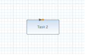
When you drag and drop the "Two Tasks" tool onto the canvas, you should see something like this:
The reason only one Task shows up is because the other (Task 1) is being covered up. By default, all of the objects defined in the tool are placed at the same cursor location. You can specify a horizontal and vertical offset for each object like this:
					<object type="Task" id="task1"/>
					<object type="Task[x=100,y=100]" id="task2"/>
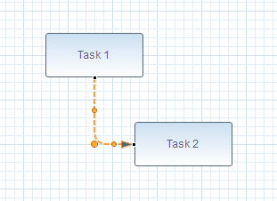
Now when you drop this onto the canvas, it looks much better:
You can also assign a name, or any other BPMN2 Task attribute for that matter, like so:
					<object type="Task[$name='First']" id="task1"/>
					<object type="Task[$name='Second',x=100,y=100]" id="task2"/>
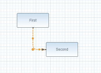
Which then looks like this:
Now let's take a closer look at the SequenceFlow object. This object requires the IDs of the source and target elements; these are defined in the preceding two Task definitions. The IDs are for reference by the tool creation element only - they are not the object's final IDs when they are created. Thus, this SequenceFlow object definition connects the object whose ID is "task1" to the object with ID "task2". Pretty straightforward stuff.
You can also define more complex arrangements of BPMN2 model elements, including elements nested inside other elements (e.g. flow elements inside a SubProcess or Lane.) Please refer to the Core Extension Points document for a more detailed description of the object definition language.


