Notice: this Wiki will be going read only early in 2024 and edits will no longer be possible. Please see: https://gitlab.eclipse.org/eclipsefdn/helpdesk/-/wikis/Wiki-shutdown-plan for the plan.
Difference between revisions of "Using MOOSE with ICE"
(→Viewing the 3D Plant (RELAP-7 only)) |
(→Viewing the 3D Plant (RELAP-7 only)) |
||
| Line 234: | Line 234: | ||
[[File:ICE_MOOSEPlantViewTools.png]] | [[File:ICE_MOOSEPlantViewTools.png]] | ||
| − | * '''Wireframe''' - Clicking this will toggle the plant's wireframe on and off; this allows you see how the meshes for the rendering engine are constructed.<br /><br />[[File:ICE_MOOSEPlantViewWireframe.png]]<br /><br />In certain cases, this may be useful for verifying the plant model before running a simulation. For instance, pipe components in RELAP-7 have a property called "n_elems" representing the number of cylindrical cross-section slices along the pipe's length. By switching to wireframe mode, the user can see the same number of cylindrical sections stacked together that represent the pipe's physical construction. | + | * '''Wireframe''' - Clicking this will toggle the plant's wireframe on and off; this allows you see how the meshes for the rendering engine are constructed.<br /><br />[[File:ICE_MOOSEPlantViewWireframe.png|625px|]]<br /><br />In certain cases, this may be useful for verifying the plant model before running a simulation. For instance, pipe components in RELAP-7 have a property called "n_elems" representing the number of cylindrical cross-section slices along the pipe's length. By switching to wireframe mode, the user can see the same number of cylindrical sections stacked together that represent the pipe's physical construction. |
* '''Camera Orientation''' - You can re-orient the rendering engine's default camera view by clicking on the ''Camera Orientation'' button. The default orientation—YZ—is the standard ''<i, j, k>'' physics orientation with the Y axis increasing to the right, the Z axis increasing upwards, and the camera looking at the YZ-plane along the positive X axis.<br /><br />In the same "Camera Orientation" menu, we provide two alternative default orientations: the XY orientation shows the XY-plane from along the positive Z axis, and the ZX orientation shows the ZX-plane from along the positive Y axis. Selecting ''Reset to current default'' will snap the camera back to the origin view should you ever get lost. | * '''Camera Orientation''' - You can re-orient the rendering engine's default camera view by clicking on the ''Camera Orientation'' button. The default orientation—YZ—is the standard ''<i, j, k>'' physics orientation with the Y axis increasing to the right, the Z axis increasing upwards, and the camera looking at the YZ-plane along the positive X axis.<br /><br />In the same "Camera Orientation" menu, we provide two alternative default orientations: the XY orientation shows the XY-plane from along the positive Z axis, and the ZX orientation shows the ZX-plane from along the positive Y axis. Selecting ''Reset to current default'' will snap the camera back to the origin view should you ever get lost. | ||
Revision as of 18:48, 16 December 2014
The capabilities in this document are brand new and while we assert that they work, that may not be the case on all systems for all users. Problems should be reported directly to the ICE team by sending an email to the project list, ice-dev <at> eclipse.org, or following the instructions to report bugs on our Bugzilla.
Contents
Introduction
This document is designed to outline the basic steps of setting up and using the MOOSE plug-ins in ICE. ICE currently supports four MOOSE-based applications: MARMOT, BISON, RELAP-7 and RAVEN. Although this tutorial was created with BISON in mind, the steps for using ICE with MARMOT, RELAP-7 and RAVEN are the same.
There are two different tasks for the input generation and launching of MOOSE products within ICE:
- MOOSE Model Builder - Generates a custom input file necessary to launch a MARMOT, BISON, RELAP-7 or RAVEN job.
- MOOSE Launcher - Initiates the MARMOT, BISON, RELAP-7 or RAVEN codes to run on a local or remote system using the files generated from the MOOSE Model Builder. Also includes a utility for generating YAML and action syntax files necessary to use the MOOSE Model Builder.
Installation and Configuration
Follow the instructions in the Getting ICE article to download and install the latest version of ICE on your system.
Prerequisites
You should have the MOOSE environment installed, either your local or remote machine. Instructions for installing MOOSE can be found here.
Additionally, you should have MARMOT, BISON, RELAP-7 or RAVEN compiled and ready to run. Contact the development teams of these projects on the rules and regulations for obtaining these codes.
MOOSE Perspective
ICE supports numerous plugins from different areas of science, and as a result it can sometimes be difficult for new users to make sense of all the different windows, panels and tabs in the workbench. To address this issue for MOOSE users, ICE now includes a MOOSE Perspective which pares down UI components to only those that are necessary for MOOSE-based plugins.
To access the MOOSE Perspective, use the the ICE toolbar at the top and navigate to:
Window > Open Perspective > Other...
Select MOOSE in the window that pops up and click OK. Alternatively, you can also access the same pop-up menu by clicking the Open Perspective button in the upper right-hand corner of the ICE workbench.

Once the MOOSE Perspective opens, you should notice the workbench now contains fewer UI components, and should resemble something like this:

While it's not necessary to switch to the MOOSE Perspective to use MOOSE-based plugins, it has been included for convenience.
Generating YAML and Action Syntax Files
Like any MOOSE-based GUI, ICE relies on generated YAML and action syntax files to specify the rules of creating input files. To simplify this task, ICE includes a utility that will generate these files (either locally or remotely), clean them up, and place them in the appropriate local directory for ICE to use. All that is required of the user is to specify where and on which machine their MOOSE codes are installed.
This task must be completed at least once for every installation of ICE before the MOOSE Model Builder can be used. It's also a good idea to periodically re-run this utility to keep ICE's YAML and action syntax files in sync with any updates to your MOOSE-based codes.
To use this utility, begin by clicking the green "+" button in the Item Viewer, located on the left-hand side of the ICE workbench.

This will prompt a window to pop up; select the MOOSE Launcher Item and click Finish. The MOOSE Launcher will load in the main workbench area.

From the list of Available Executables, select "Generate YAML/action syntax files".

Next, specify where your MOOSE-based codes are installed, either locally or remotely. A list of hosts used at ORNL is displayed by default, however, additional hosts can be added by clicking the "+" button to the right of the Hosts table.

When adding hosts, set the Execution Path to the trunk directory of the machine's MOOSE installation. For example, if I have BISON on a machine with the following structure:
/home/user/trunk/bison/bison-opt
I would set the execution path in ICE to be:
/home/user/trunk
If you are launching on a remote machine, also be sure that you have appropriate privileges for the execution path. Once you are finished, save your settings by clicking the floppy-disk icon in the upper-left hand corner of the ICE workbench (or ⌘+S / Ctrl+S). If you make any subsequent changes to the MOOSE Launcher form, you will have to re-apply them by saving the form in the same way.

Lastly, use the Process menu in the upper right-hand corner; select the Launch the Job task from the drop-down menu and click the Go! button.

This step will launch a script on your designated machine that checks which MOOSE-based codes you have installed, generates the appropriate files, removes any extraneous header/footer text, and places them in your /home/<user>/ICEFiles/default/MOOSE directory.
Creating Input
To create an input file for a MOOSE problem, there are two ways you can get started: creating an input file from scratch, or importing an already existing file to modify.
Creating an Item
If you'd like to start from scratch, begin by clicking the green "+" button in the Item Viewer, located on the left-hand side of the ICE workbench.
This will prompt a window to pop up; select the MOOSE Model Builder Item, and click Finish.
Alternatively, if you'd like to import an already existing *.i file to modify, click the yellow item import arrow located at the top of the ICE workbench.

A wizard will pop up prompting you to specify two things: the *.i file you'd like to import from your filesystem, and what kind of Item you'd like to import it into.

Use the Browse... button to select your input file, and set the item type to MOOSE Model Builder. Click Finish when you're done and ICE will import the file data.
Regardless of how you decide to begin creating your input file, once the MOOSE Model Builder loads, you will see a workbench that looks like the follow. Make note of the two tabs highlighted: the Tree View and Properties tabs, as we'll be using them quite a bit in the following section.

Note that all the panels, tabs and windows in ICE can be re-sized and moved around for the configuration that best suits your needs.
Constructing the Tree
Before be begin constructing our problem, the first order of business is to specify which MOOSE application we're defining a problem for. Use the drop-down menu on the Tree View, select one of the options; in this example, we'll be modifying a BISON problem.

At this point, a fully loaded set of blocks should appear in the Tree View. If you imported your data from an already existing file, you'll notice the data has been loaded into any blocks that are checked off. If you started from scratch, none of the blocks will be checked off yet.

We're now ready to begin using the Tree View to add, delete and modify blocks.
Expanding and Collapsing Subblocks
If you imported data from an already existing input file, you will likely notice some block names with a small arrow next to them. This indicates that the block contains subblock structures beneath it. To access these subblocks, simply click the small arrow and the subblocks will expand. Clicking this arrow again will collapse the subblocks.

Adding and Deleting Blocks
If you'd like to add a subblock, first select the parent block you'd like to add it to. Next, click the green "+" button located at the top right-hand corner of the Tree View. Alternatively, you can also right-click the parent block, and select Add Child from the context menu that appears.

Doing this will prompt a pop-up dialog to appear. This dialog contains a list of all possible subblocks that can be added, according to rules outlined in the YAML files generated earlier. Each block that appears in the list has its own unique set of parameters, with the exception of BlankBlocks, which are—as their name suggests—blocks that are totally devoid of any information.

Once you've selected a subblock to add, click OK, and it will be added in the Tree View. Use the arrow next to the parent block to expand/collapse the list of subblocks.
Similarly, to delete a block, select the particular block you'd like to remove, and click the red "x" button located at the top right-hand corner of the Tree View. You can also delete a block by right-clicking on it and selecting Delete Child from the pop-up context menu.

If the red "x" button is greyed-out for a particular block, this means that deletion has been disabled. This is true for all top-level blocks.
Renaming Blocks
To rename a block, right-click on the block in question and select Rename from the context menu that appears. If the renaming option is greyed-out from the context menu, this means that renaming has been disabled for this block. Once again, this is true for all top-level blocks.
Editing Parameters
Each block has a set of parameters associated to it. The default list of parameters for each block is drawn from the YAML file that was generated earlier. To add, remove or modify parameters associated to a block, first select a block from the Tree View. A table of parameters will then appear in the Properties tab referenced earlier.
The parameters table displays a parameter name, value and the option for an in-line comment, which can all be edited directly in this table. When written out to file, each parameter will be written to one line in the form:
name = value # comment
Additional parameters can be added by clicking the "+" button to the right of the parameter table; parameters can be similarly deleted by clicking the "-" icon.

Next to each parameter row, you'll also notice an Enabled checkbox. Toggling this option on means that the parameter associated to it will be written out normally in the file created. Toggling this option off will cause the entire line to be commented out, and thus, won't be used during the problem runtime.
Note that if you created a MOOSE Model Builder by importing data from an already existing input file, ICE automatically parses any in-line comments or commented out lines (non-sensitive to leading whitespaces). This will be reflected in the Enabled and Comment columns of the parameters table.
Lastly, some blocks contain a special type parameter, such as the `Executioner` block, which affects the list of parameters associated to the block. In these special instances, an additional drop-down menu will appear in the Property tab, above the parameters table.

By setting the type of the block ICE automatically repopulates the parameter table according to the rules defined by the YAML specification.
Viewing the 3D Plant (RELAP-7 only)
For RELAP-7 problems, ICE includes an interactive 3D Plant View to visualize the physical respresentation of the problem. To access the Plant View, click the Plant View tab located at the bottom of the main MOOSE Model Builder panel.

Note that the Plant View tab is only visible if RELAP-7 has been selected as the MOOSE application in the Tree View; the Plant View will not be accessible for any other MOOSE applications.
This view draws data from the Components block in the Tree View; if you have valid components in the Components block, then they should begin rendering now. Before we go on, there are a few things to note about using the Plant View. First, only components that are currently enabled in the Tree View (i.e. have a checkmark) are rendered. This way, components can easily be turned on and off without having to delete them entirely. And secondly, the Plant View updates in real time; any changes that you make to components in the Tree View will be reflected immediately such as adding, removing, re-positioning or re-orienting components.

Once your plant components have rendered, you can move around the 3D space by using the following keyboard controls:
| Movement | Key | Rotation | Key |
|---|---|---|---|
| Left | A | Rotate clockwise | Q |
| Right | D | Rotate counterclockwise | E |
| Up | C | Pivot left* | ← |
| Down | Space | Pivot right* | → |
| Zoom in | W | Pivot up* | ↑ |
| Zoom out | S | Pivot down* | ↓ |
* The camera viewing-angle can also be pivoted by left-clicking and dragging
Lastly, the Plant View has 3 tools located in the toolbar above the 3D viewing window.

- Wireframe - Clicking this will toggle the plant's wireframe on and off; this allows you see how the meshes for the rendering engine are constructed.
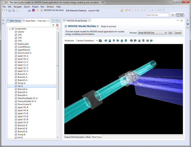
In certain cases, this may be useful for verifying the plant model before running a simulation. For instance, pipe components in RELAP-7 have a property called "n_elems" representing the number of cylindrical cross-section slices along the pipe's length. By switching to wireframe mode, the user can see the same number of cylindrical sections stacked together that represent the pipe's physical construction.

- Camera Orientation - You can re-orient the rendering engine's default camera view by clicking on the Camera Orientation button. The default orientation—YZ—is the standard <i, j, k> physics orientation with the Y axis increasing to the right, the Z axis increasing upwards, and the camera looking at the YZ-plane along the positive X axis.
In the same "Camera Orientation" menu, we provide two alternative default orientations: the XY orientation shows the XY-plane from along the positive Z axis, and the ZX orientation shows the ZX-plane from along the positive Y axis. Selecting Reset to current default will snap the camera back to the origin view should you ever get lost.
- Save Image - Click this will prompt a pop-up window to save a .png image of the current Plant View to your local filesystem.
Creating the File
Once you have edited your blocks and associated parameters to your liking, the last step is to write them to file. Any block in the Tree View with a checkmark next to it will be written to file, and conversely, and block without a checkmark will not. Ensure that you've correctly selected all the necessary blocks. Save your work by clicking the floppy-disk save icon (or ⌘+S / Ctrl+S).
At the top of the MOOSE Model Builder tab, specify the name of the file you'd like to write, set the Process drop-down menu to "Write MOOSE File", and click the Go! button.

This will write the contents of your Tree View to the specified filename, and will be placed in your /ICEFiles/default directory. If you wish to review the file before moving onto the next section, you can do so by using the ICE toolbar and navigating to:
File > Open File...
Launching a MOOSE Job
Once you've generated appropriate input files, launching a MOOSE job is a relatively simple task.
To get started, click the green "+" button in the Item Viewer once more to create a new ICE Item.
Select MOOSE Launcher from the menu that pops up and click Finish.
A form will appear in the main ICE workbench area. This form contains the information necessary for launching a MOOSE problem.
Selecting the MOOSE Product
The first piece of necessary information is to set which MOOSE-based application you'd like to run. From the list of Available Executables, select an application,

Immediately apply your choice by clicking the save button in the upper left-hand corner of the workbench (or ⌘+S / Ctrl+S).
Selecting the Input File(s)
From the Input File(s) drop-down menu, select an appropriate MOOSE input file. This drop-down menu displays all *.i files that were in the /ICEFiles/default directory at the time the MOOSE Launcher was created. If you created your own input file in the previous step using the MOOSE Model Builder, this file should appear in the list of available files.
If you'd like to use an input file not found in this list, click the Browse... button; a file browser will pop up for you to locate the file you'd like to use. Once you've selected a file, it will be imported into the /ICEFiles/default directory.

If your problem requires additional files, such as a mesh, peaking factors, or power history data, do the same for these as well.
The next step is to tell ICE which machine your MOOSE code will be run on, either locally or remotely. A list of hosts used at ORNL is displayed by default, however, additional hosts can be added by clicking the "+" button to the right of the Hosts table.
When adding hosts, set the Execution Path to the trunk directory of the machine's MOOSE installation. For example, if I'm launching BISON on a machine with the follow structure:
/home/user/trunk/bison/bison-opt
I would set the execution path in ICE to be:
/home/user/trunk
If you are launching on a remote machine, also be sure that you have appropriate privileges for the execution path.
Setting Parallel Execution (Optional)
Optionally, if you'd like to take advantage of parallel processing, you may specify the number of MPI process and/or Intel Thread Building Block (TBB) threads.

To use multiple MPI processes, change the marked field to an integer value anywhere between 1 and 10000. Note that mpirun must be specified in the host machine's PATH variable. If you choose not to change this field, the default value of 1 MPI process is used.
To use multiple TBB threads, change the marked field to an integer value anywhere between 1 and 256. Note that the host machine must have Intel TBB support. If you choose not to change this field, the default value of 1 TBB thread is used.
Launching the Problem
Once the input file(s), host, and any parallel execution options are specified, save your settings. If you make any subsequent changes to the MOOSE Launcher form, you will have to re-apply them by saving the form in the same way.
Lastly, use the Process menu in the upper right-hand corner; select the Launch the Job task from the drop-down menu and click the Go! button.
Depending on your host machine's configuration, you may be prompted for login credentials.
You should shortly begin seeing the standard console output in ICE as your problem begins to solve.
FAQ (Frequently Asked Questions)
An FAQ for MOOSE users can be found here. If you have any additional questions that are not addressed in this document, email our project development list at ice-dev <at> eclipse.org.
Visualizing Output
To visualize MOOSE output in ICE, visit our Visualizing Output with ICE tutorial.