Notice: this Wiki will be going read only early in 2024 and edits will no longer be possible. Please see: https://gitlab.eclipse.org/eclipsefdn/helpdesk/-/wikis/Wiki-shutdown-plan for the plan.
Difference between revisions of "Tutorial: Raspberry Pi GPIO with OSGi Services"
(Created page with "<!-- This CSS wraps code blocks in pretty boxes --> <css> .mw-code { background-color: #fafafa; padding: 20px; border-color: #ddd; border-width: 3px; border-sty...") |
|||
| Line 80: | Line 80: | ||
Each GPIO digital pins have two modes: output and input. For output, each pin can be in either the 'HIGH' state, or the 'LOW' state, and the control of the pin state is what we would like to manipulate to give our application behavior. After connecting a single LED, changing the output on a given pin to HIGH will turn the LED on, while setting to low will turn it off. See [https://projects.drogon.net/raspberry-pi/gpio-examples/tux-crossing/gpio-examples-1-a-single-led/ this page for a description of how to setup such an LED]. | Each GPIO digital pins have two modes: output and input. For output, each pin can be in either the 'HIGH' state, or the 'LOW' state, and the control of the pin state is what we would like to manipulate to give our application behavior. After connecting a single LED, changing the output on a given pin to HIGH will turn the LED on, while setting to low will turn it off. See [https://projects.drogon.net/raspberry-pi/gpio-examples/tux-crossing/gpio-examples-1-a-single-led/ this page for a description of how to setup such an LED]. | ||
| − | + | We would like to use OSGi services to simplify software access to devices connected to the GPIO digital pins. Here's a picture of a Raspberry Pi setup with an LED connected to GPIO digital output pin 0, as per the [https://projects.drogon.net/raspberry-pi/gpio-examples/tux-crossing/gpio-examples-1-a-single-led/ instructions here]. This is the setup that I use to test the services described below | |
| − | + | ||
| − | + | ||
| − | + | ||
| − | We | + | |
[[File:Ledsetup.png]] | [[File:Ledsetup.png]] | ||
Revision as of 17:51, 1 August 2014
Introduction
This tutorial shows how to access the Raspberry Pi GPIO using OSGi Services. OSGi Services makes the application use of GPIO pins simpler, easier, and more dynamic.
An OSGi Service for GPIO Pin Output
Each GPIO digital pins have two modes: output and input. For output, each pin can be in either the 'HIGH' state, or the 'LOW' state, and the control of the pin state is what we would like to manipulate to give our application behavior. After connecting a single LED, changing the output on a given pin to HIGH will turn the LED on, while setting to low will turn it off. See this page for a description of how to setup such an LED.
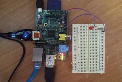
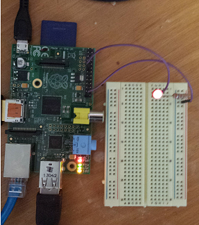
We would like to use OSGi services to simplify software access to devices connected to the GPIO digital pins. Here's a picture of a Raspberry Pi setup with an LED connected to GPIO digital output pin 0, as per the instructions here. This is the setup that I use to test the services described below
For OSGi services, we start by creating a service interface declaring the methods for accessing a single GPIO pin. Here is the IGPIOPinOutput service interface:
public interface IGPIOPinOutput extends IGPIOPin {

	public boolean getState();

	public void setState(boolean value);

	public boolean toggle();

	public void pulse(long duration, boolean pulseState);

	public void blink(long delay, long duration, boolean blinkState);

}
For this tutorial, we will be interested only in the getState and setState methods from this service interfaces. Note that we can create as many instances of this service interface as desired, but are limited by the GPIO device itself, which has two rows of 10 pins for a total of 20 physical pins.
Since the implementation of this interface already exists, all we need to do use the IGPIOPinOutput service is to write our application code so that OSGi service instances of this type are accessed for the pins we are interested in manipulating.
To find and use an instance of IGPIOPinOutput we can use one of several OSGi mechanisms: 1) Declarative Services; 2) ServiceTracker; 3) BundleContext. For this tutorial, we will use a very simple ServiceTracker. The full code for this example can be located in the start method of this test code. The important fragments from this example are the implementation of the addingService method, which is executed when instances of IGPIOPinOutput are registered in the OSGi service registry
public IGPIOPinOutput addingService(ServiceReference<IGPIOPinOutput> reference) {
    System.out.println("Adding GPIO Pin Output service.   id="+reference.getProperty(IGPIOPinOutput.PIN_ID_PROP));
    IGPIOPinOutput pin = context.getService(reference);
    System.out.println("  current pin state is "+(pin.getState()?"HIGH":"LOW"));
    System.out.println("  setting state to HIGH");
    pin.setState(true);
    return pin;
}
Note that when the IGPIOPinService is added, the service.setState(true) method is called, which will set the state of the pin to HIGH, turning on the LED connected to that pin.
As well, we will implement removedService which is executed when instances of IGPIOPinOutput are unregistered.
public void removedService(ServiceReference<IGPIOPinOutput> reference,
                           IGPIOPinOutput service) {
    System.out.println("Removing GPIO Pin service. id="+reference.getProperty(IGPIOPinOutput.PIN_ID_PROP));
    System.out.println("  setting state to LOW");
    service.setState(false);
}
When the service is removed, the service.setState(false) is called, which will set the state of pin 0 to LOW, turning off the LED connected to that pin.
When this test bundle is run on a Raspberry Pi (using Java8+Equinox 4.4), this appears on the OSGi console:
osgi> start 3
Adding GPIO Pin Output service.   id=0
  current pin state is LOW
  setting state to HIGH
TestGPIOPinInputListener.handleInputEvent(event=GPIOPinInputEvent [getPinId()=2, state=false])
And the LED lights up
If we then stop this test bundle, this appears on the OSGi console
osgi> stop 3
Removing GPIO Pin service. id=0
  setting state to LOW
and the LED goes out.
Here is a short video showing the running of this test code by using the Apache Webconsole.
Related Articles
Getting Started with ECF's OSGi Remote Services Implementation
Asynchronous Proxies for Remote Services
Building your first Asynchronous OSGi Remote Service Tutorial


