Notice: this Wiki will be going read only early in 2024 and edits will no longer be possible. Please see: https://gitlab.eclipse.org/eclipsefdn/helpdesk/-/wikis/Wiki-shutdown-plan for the plan.
Papyrus/customizations/robotics/systemdes
Contents
System design principle
Designing a system is assembling defined components in order to create a consistent communicating structure of components.
How to edit
A set of component instances that are wired together via their ports. At this level, it is also possible to configure component instances.
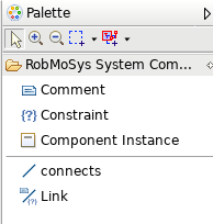
The palette shown above enables the user to declare new component instances (besides the possibility to declare comments and constraints).
After an instance is added, use the property view to assign a component type. Once the type is assigned, parameter settings can be updated via the property view as well (provided that the component definition has assignable attributes).
After a type is assigned, the ports appear (choose a graphical position manually) and can be connected.
System design from scratch
Forewords
Please read here for the description of the example taken as reference in this section.
Step-by-step procedure
We may now define the system whose default name is System:
- We create a new Robotics project with “Create a system” as the main objective.
- Then, we click on “Next” and choose the project’s name, for example fromscratch_system, before clicking on “Finish”.
- We now click on the “Fromscratch_system_diagram” view in the “Notation Views” part of the “Welcome” panel.
- We drag-and-drop a Component Instance from the Palette to the System system.
- We “Choose component type” as Workspace matches/mult_server.compdef.uml/Mult_server.
- We name it main.
- We drag-and-drop two other Component Instance from the Palette to the System system.
- We “Choose component type” as Workspace matches/mult_client.compdef.uml/Mult_client.
- We name them left and right.
- We connect the respective ports with the connects link of the Palette.
- We select the left component and in the Properties view/Parameters Settings tab, we change the init_yVal to 3.
- We select the right component and in the Properties view/Parameters Settings tab, we change the init_yVal to 2.
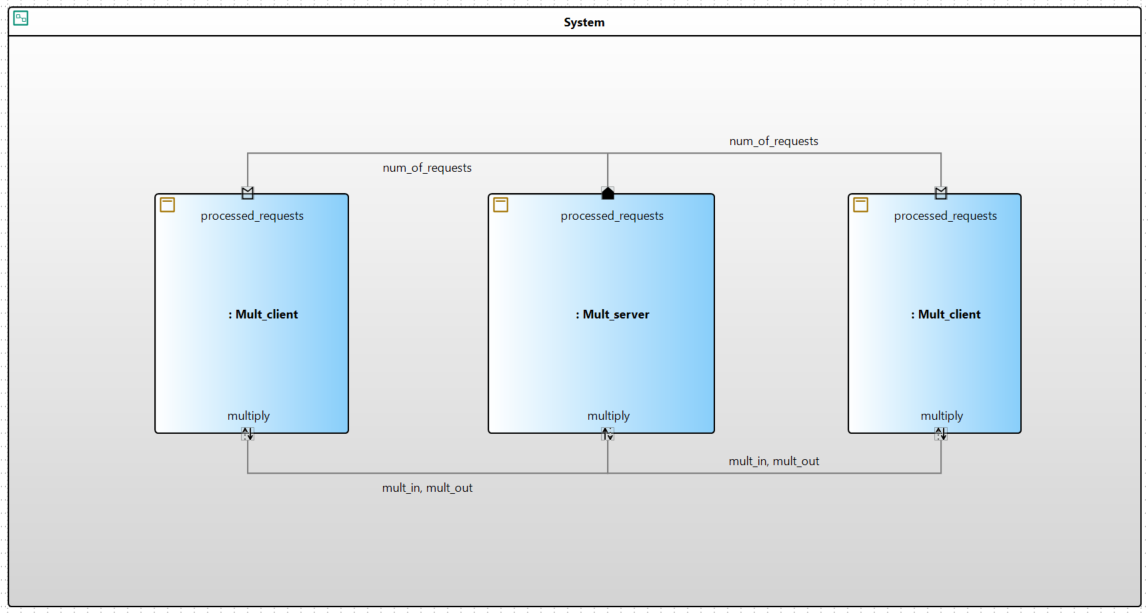
Here is the resulting diagram:
Position with respect to the robotics domain
A component definition is a tier-3 activity, i.e. an activity that is typically done by a system builder. A system builder designs the global architecture by assembling components and adjusting settings. He can for example re-adjust specified parameters in the Properties view of a component’s Parameter set.


