Notice: this Wiki will be going read only early in 2024 and edits will no longer be possible. Please see: https://gitlab.eclipse.org/eclipsefdn/helpdesk/-/wikis/Wiki-shutdown-plan for the plan.
Koneki/LDT/Technical Discussions/Bandwidth estimation tool specification
Contents
Introduction: a generic bandwidth estimator
This document describes the specifications of a generic bandwidth estimator. This tool estimates the bandwidth which is use by one device with different communication protocols during one specified period. So, this tool provides to set three informations.
- The behaviour of the device: when data are send and received
- The communication protocol that the device use
- The period of the estimation
Different combinations of these informations will change the bandwidth used by the device.
The estimator is qualified generic because it allows to choose which communication protocol is used by the device. Indeed, the second purpose of this tool is provide a platform where other protocols implementation could be install. These implementation have to be an Eclipse plug-in. This feature is explain in this section.
The following chapters describe:
- A general explication of how the estimator works
- The description of the user interfaces
- The model which is used to describe the data of the device (when they are send and they are generate)
- The model which is used by the estimator to store generated values for each data
- The description of the estimator architecture which provide to add new protocols
How the estimator works
The estimator needs four informations to create one estimation:
- The description of the device: which data the device will send and receive. These informations are already set into the application model.
- How this data will be use by the device: when the device will send and receive informations. These informations are set with the bandwidth estimation tool.
- Which communication protocol the device will use during its exploitation. This information is also set with the bandwidth estimation tool.
- The period of the estimation setted just before the estimation.
With the combination of these informations, the estimator can compute the bandwidth. It generates abstract data, creates a collection of the messages and estimates the bandwidth which the device will consume. The estimator never sends and receives messages. It just creates messages, and estimates their total size. So, if the device have to send one message every hours and the estimation period is one day. The bandwidth estimation will just take a few seconds.
The user interface of the estimator
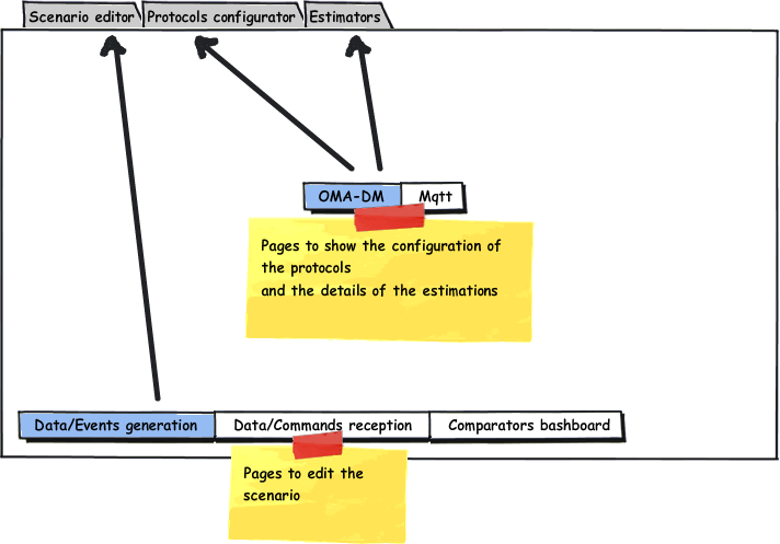
This chapter describes the user interfaces of the tool. By this way, it will by easier to understand how the tool works. The user interface is structured on few pages into three tags.
The first tab is used to edit the scenario of the estimator.
The second tab is used to edit the configuration of all protocols which are available for the estimator.
And the third tab is used to show the details of all estimations for each protocols.
The following sections describe the pages of each tags.
Scenario editor tab
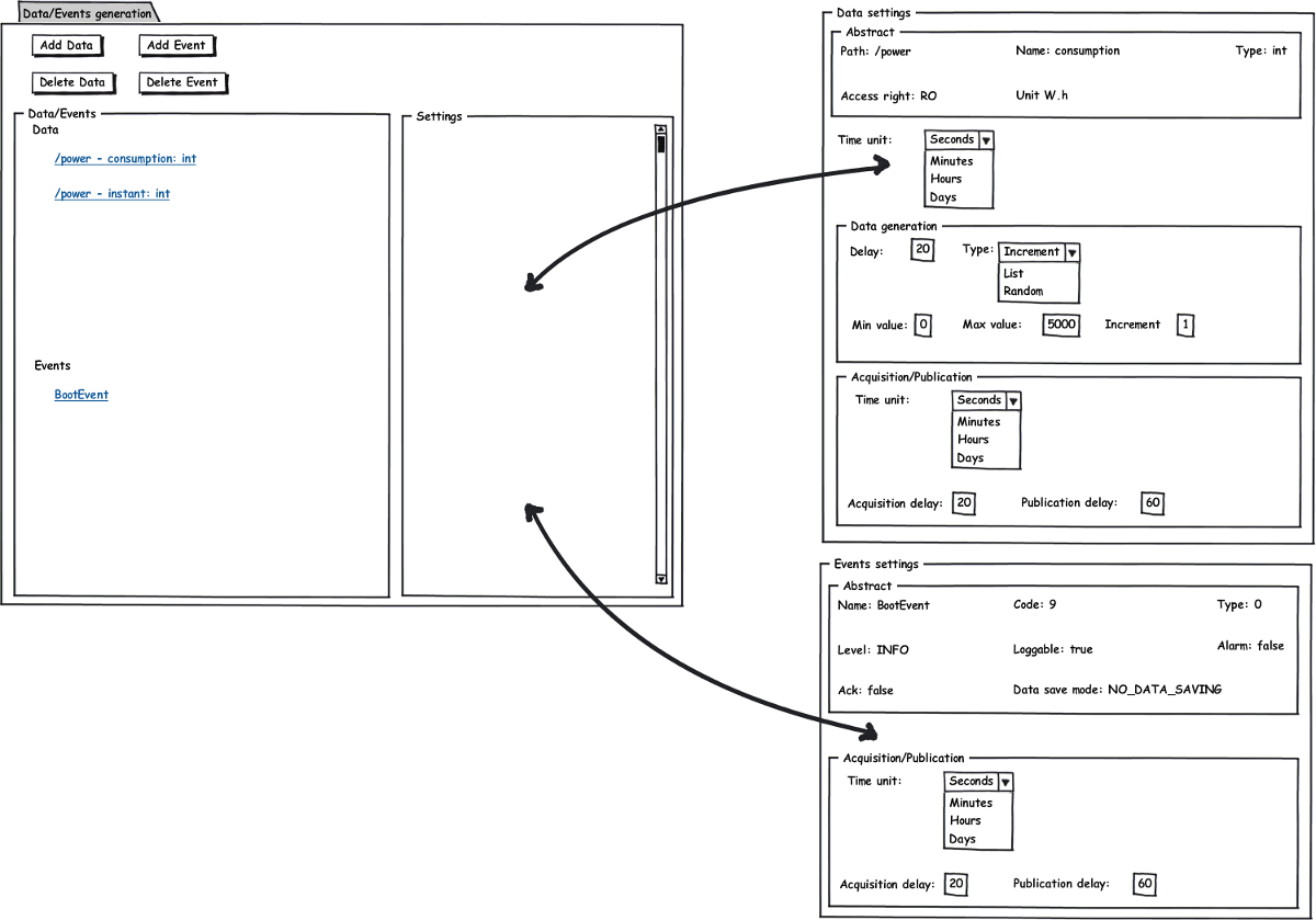
The Data/Events generation page.
This page contains the list of all data and events which the device could send during its exploitation. These informations are extract from the application model. For the estimations, the values of data and events will be automatically generate by the estimator. The bandwidth estimation is based on these artificial values. So, for each data and events this page allows to configure how the values are generate.
For the data, there are five parameters:
- Time unit in seconds, minutes, hours or days
- Generation delay: after this delay, a new value is generate
- The type of generation: Increment (values are generate by following increments values), List (generated values follow one specified list), Random (all values are generate with a random method)
- Acquisition delay: after this delay, the last value which have been generated is store to be send later
- Publication delay: after this delay, all stored values have to be send by the communication protocol
The event configuration is simpler than data configuration. There are only three parameters. The acquisition delay, the publication delay and the time unit.
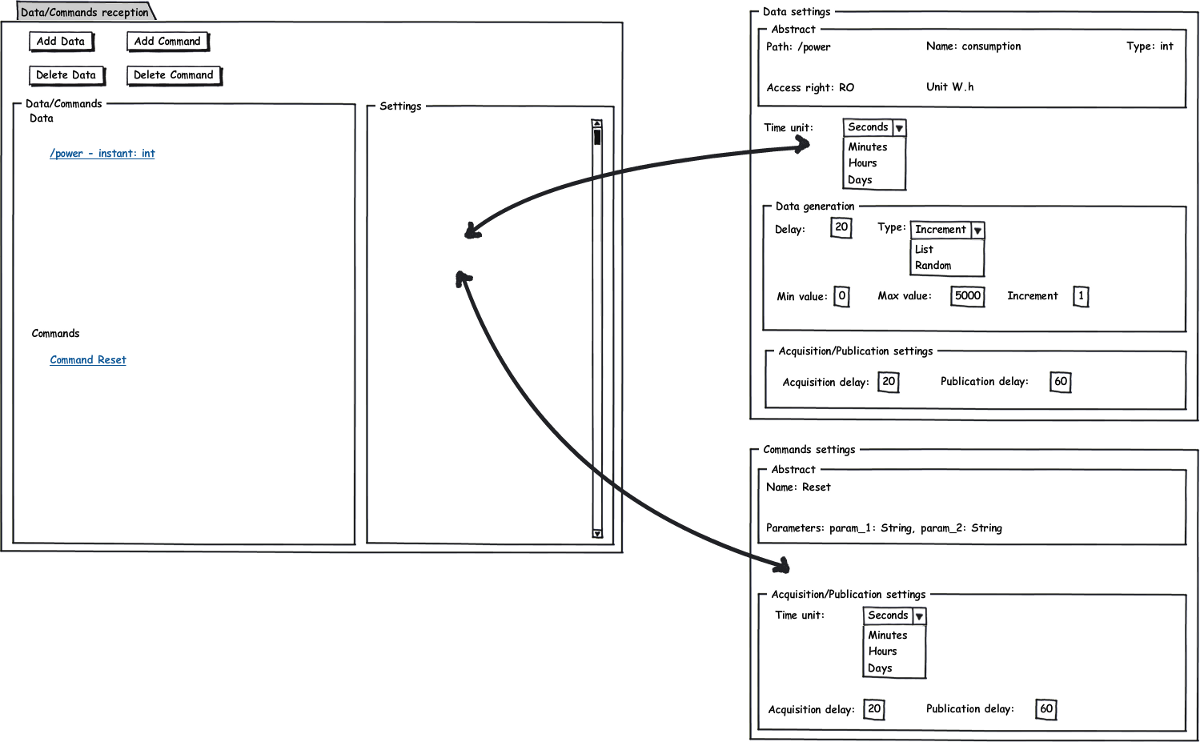
The device is also able to receive messages. Below is the details of the Commands/Data reception page.
The Data/Commands reception page.
Instead of events, data are both in reception and generation configuration page. It just means the type data is used in the two direction: upward and downward. The command configuration is the same than the events configuration for the generation page.
The following page is use to run estimations.
More explications
The estimator uses one scenario to estimate the bandwidth for one period.There are three types of informations into the model: Data, Event and Command. For Events and Commands there are two important parameter: the acquisition delay and the publication delay. It means after each acquisition delay one new data (event or command) is generate and after each publication delay each data which have been stored and haven't been published are published. For Data, the procedure is little more complex. After each generation delay, a new value is generate. After the acquisition delay only the generated value is acquire. All others are delete. Then, the procedure to publish Data is the same than Events or Commands.
For example, the model has one data, an integer, its minimum value is 1 and its maximum value is 5. One new value is generate each 10 seconds. The acquisition delay is 30 seconds, the publication delay is 60 seconds and this scenario is executed during 120 seconds. So, 12 values will be generate and only 4 values will be acquired: the 3rd, 6th, 9th, 12th. Then, only 2 groups of values will be published, the [3rd,6th] and the [9th,12th].
Illustration
| Date | 0 | 10 | 20 | 30 | 40 | 50 | 60 | 70 | 80 | 90 | 100 | 110 | 120 |
| Generated value | 1 | 2 | 3 | 4 | 5 | 1 | 2 | 3 | 4 | 5 | 1 | 2 | 3 |
| Time to store value | X | X | X | X | |||||||||
| Time to send values: [sent values] | X:[4,2] | X:[5,3] |
The bandwidth estimations page
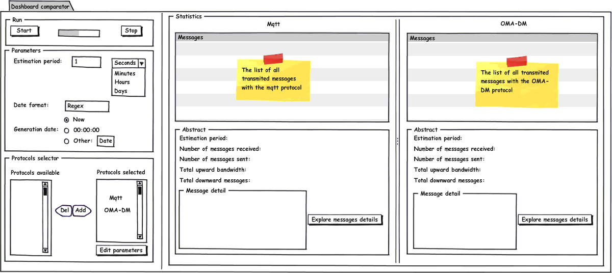
This is the most important page. It provides to run different estimations in the same time.
The "Parameters" box contains three informations.
- The estimation period sets the time of the estimation.
- The date format allows users to choose which date format it prefers
- The generation date allows to set the initial value of the date.
The "Protocols selector" allows to select which protocols will be use during the estimation. The tool offers to select more than one communication protocol. So, in the same time, it's possible to compare different bandwidths of different protocols.The configuration of each communication protocol is settable by clicking on the button "Edit parameters". The following chapter describes the pages to configure one communication protocol.
Once the estimations are terminate all generate messaged are show into the table "Messages". The detail of the selected message in the table is show into the "Message detail" box.
The full details (specific for one protocol) are available by clicking one the button "Explore messages details". There is an example of an estimation detail page in this section.
The statics of each estimations are show into the abstract boxes: the number of messages which are send and receive by the device, and the total bandwidth which is consume.
Protocols configuration tab
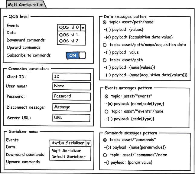
The protocol configuration tab contains all pages to configure each protocols which are available for the estimator. So, each pages are specific for each protocols. Below is one configuration example with the MQTT protocol.
MQTT configuration page
The details of this page is based on the specifications of the MQTT protocol.
Qos level
For each type of information (data, events and commands) the configuration page provide to chose which QOS is associate.
Users can also choose to send a subscribe message before to receive a new command.
Connection parameters
It's the classical fields to set the connexion settings. Users can also set the message which is eventually send after the disconnection of the device.
Serializer name
For each type of information (data, events and commands) the configuration page provides to chose which serializer is associate. This feature provides to set how the payload is serialize for each MQTT messages. For example, the users could choose a JSON serializer for the data and one binary serializer for the events.
Data/Commands/Events messages pattern
There are many ways to transform the informations (data/commands/events) in MQTT messages. So the configuration page offers to choose which pattern is the best for the application. The patterns offer to broadcast a lot of little messages or few huge messages. For example, with the event pattern "asset/events" each messages will contains all events with their name, code and type. If there are lots of events, MQTT messages could become very huge. whereas with the pattern "asset/events/name" messages will only contain the code and the type for one event. But the number of broadcast messages will increase. The users will have to chose the best pattern for its application.
Estimators tab
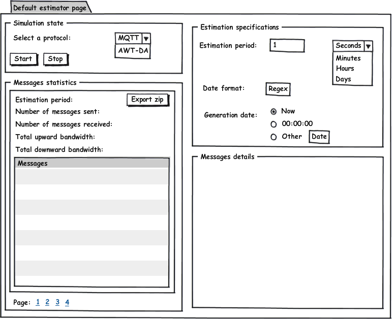
The default estimator page
The estimator tab shows the basic informations about the estimation. These informations are the same for each protocol. The purpose of this tab is contain pages for specific protocols which have to show more informations about the estimation. This page should be present in the plug-in which implement the client protocol.
Below is the default page to show informations about the estimations.
This page have same informations than the estimator page.
The models of the estimator
General presentation
There is one emf model to store informations about the estimations. One instance of this emf model is store into one xml file to keep the estimations into the files system. This model contains some classes to generate values for data, events and commands. The model contains also the parameters of each protocols which are used for the estimation. The description of the model is divided in two diagrams.
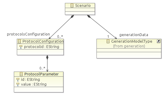
Below is the first part of the model.
The generation model type
This diagram shows one Scenario which contains two parts, the protocol parameters and the GenerationModelType. The protocol parameters is very simple. By this way, each protocol will be able to store its own informations. This part is based on dictionaries with keys and values.
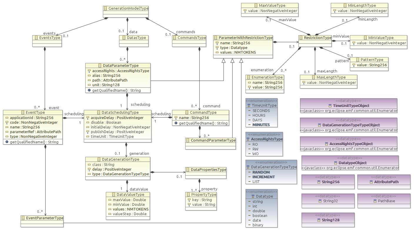
The second diagram describes the GenerationModelType.
This diagram shows how store all parameters to generate artificial values.There are three important classes: DataParameterType, CommandType and EventType. There are the entry points to get all the parameters. One instance of this classes represent one variable of the device.
The architecture of the estimator
This chapter shows the architecture of the estimator. It contains two points:
- The explication of the solution which is uses to store generated values during one estimation
- The structure of the estimator with different plug-in. This section explains how add new protocols into the estimator to increase its functionalities.
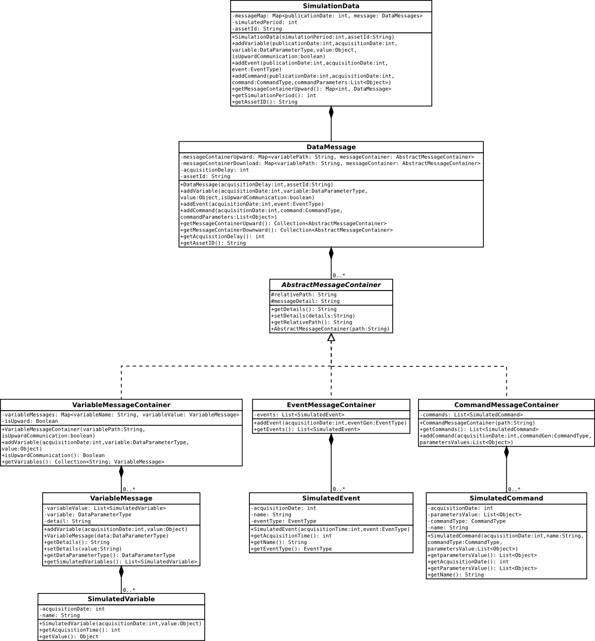
The class diagram of generated values
The generated values are stored into a model. During the estimation, the tool fills this model with generated values. Then, the client protocol, with a special interfaces, creates messages and compute the bandwidth. This model is dynamically created during each estimation. Instances of this model are not saved into the xml file.
There are links between the model of the generated values and the GenerationModelType. The VariableMessage class has an attribute DataParameterType. The SimulatedEvent has an attribute EventType. The SimulatedCommand has an attribute CommandType.
The plug-in architecture
Below is the diagram to explain the plug-in architecture of the estimator.
The three boxes on the top of the diagram represent plug-ins. The ExtensionPoint class represent an Eclipse extension point. The classes drew in blue are Java interfaces.
The first plug-in, BandwidthEstimatorModel contains the model of the estimator.
The second plug-in, BandwidthEstimationEditor contains all the user interfaces to set the model and run bandwidth estimations.
The last plug-in, AbstractBandwidthEstimator contains an extension point. Plug-ins which want to add new client protocol for the estimator have to respect this extension point. The extension point has a name (the name of the protocol which is implemented) and four interfaces. The next section defines these interfaces. The cardinalities which are associated at the interfaces are not all the same. IBandwidthEstimator and IProtocolConfigurationPage have their cardinalities equals to one because the estimator can't provide one default implementation of these interface. Instead of the others interface where the estimator provides one default implementation. For example, an implementation of the IBandwidthEstimatorPage is described in the default estimator page section.
The interfaces of the extension point
Below is the representation of all interfaces contained into the extension point.
Some of these interfaces depends on the DataMessage and SimulationData classes. They are defined into the class diagram of generated values.
The following sections are focused on IEstimationActivator and IBandwidthEstimator. The others interfaces are just a part of the user interfaces of the estimator.
The IBanwidthEstimator interface
The IBandwidthEstimator interface has six abstract methods:
- getDownwardMessageSize: return the bandwidth size which is use to receive one DataMessage
- getUpwardMessageSize: return the bandwidth size which is use to send one DataMessage
- getTotalDownwardBandwidth: return the bandwidth size to receive all the DataMessage which are into the SimulationData. The default implementation of this method add the results of getDownwardBandwidthSize for each DataMessage
- getTotalUpwardBandwidth: do the same thing than getTotalDownwardBandwidth for the upward messages
- getTotalUpwardMessages: return the number of upward messages for all the estimation
- getTotalDownwardMessages: return the number of downward messages for all the estimation
These methods return the basic informations about the current estimation. Once the estimation is terminate, these informations are showed in the estimation page.
The IEstimationActivator Interface
This interface allows to start an stop one estimation. These methods should be called from the default estimator page or from the specific estimation page of the protocol.
The method "run" returns an instance of SimulationData. This SimulationData contains the generated values and the details of messages. The method "stop" returns an incomplete instance of SimulationData. This method stop the estimation before the end. So the bandwidth estimation will be incomplete.

