Notice: this Wiki will be going read only early in 2024 and edits will no longer be possible. Please see: https://gitlab.eclipse.org/eclipsefdn/helpdesk/-/wikis/Wiki-shutdown-plan for the plan.
Graphical Modeling Framework/Concepts/Constraints
Contents
Expression Support
GMF uses value expressions in various constructs of the mapping model, i.e. element initializers, link constraints, audits, etc. Value expressions represent linguistic formulas that yield values when evaluated in a context. The way contexts are derived and what value types are required is dependent on the GMF mapping model in use and is described below.
Value expressions are defined using a body and language. The body text states how the resulting value is to be calculated, while a language enumerator indicates the language in which the expression is stated.
Current supported languages are:
OCL
Object Constraint Language (OCL) is capable of using the Ecore meta-model attribute access, operation calls, and reference navigation. It is a powerful and preferred tool for effective construction of query expressions on meta-models.
regexp
Regular expressions are defined in EDataType context and evaluated against a data type value which is due to EMF framework convertible to string, as required by regexp. In comparison to OCL, this language is not meta-model aware and is purely value-oriented. The only resulting value a regexp expression can produce is of boolean type, indicating that a context value matches the given pattern.
nregexp
Negated variant of regexp used to address those use-cases where it is extremely difficult to formulate a corresponding pattern to return true, but straightforward to express in the negated form.
Java
Java is usually the option when the expression logic represents excessive complexity or requires direct access to Ecore reflective API, which is possible with Java and OCL but not with the rest of the supported languages . While the other language alternatives can be validated at modeling time and interpreted at runtime, a Java expression implementation is to be provided by the user. Thus, the expression body part does not contain the actual java source code. Instead, the body holds a Java identifier which becomes the basis for deriving the name for corresponding Java element in the generated code. The common convention of Ecore meta-model has been adopted and operation skeleton for every Java expression is generated.
The skeleton has appropriate context environment variables as arguments, and its default implementation simply throws an exception reporting ‘missing user implementation’. As soon as the user provides a custom implementation the operation should be marked as @generated NOT in order to preserve it across generation sessions. The class that will be the owner of the skeleton operation is dependent on the type of the expression construct in use.
That is, the following method will be generated for all Java constraints in diagram.part.XXXVisualIDRegistry.java:
/**
 * @generated
 */
private static boolean isModelElement_2061(ModelElement domainElement) {
  // FIXME: implement this method
  // Ensure that you remove @generated or mark it @generated NOT
  throw new UnsupportedOperationException(
      "No java implementation provided in 'isModelElement_2061' operation"); //$NON-NLS-1$
}
However, if .gmfgen > Gen Expression Provider > Gen Java Expression Provider > Inject Expression Body is set to true (not the default), then the "body" specified in the constraint will be directly inserted into this method.
Audits
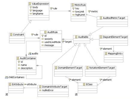
Audits represent set of rules that must hold true if evaluated on a diagram instance. Individual audits are represented by gmfmap::AuditRule and can be organized hierarchicaly into logical categories by using gmfmap::AuditContainer. Every audit defines a rule constraint which is a boolean typed specialization of gmfmap::ValueExpression. The constraint expression is to be parsed and evaluated in the context specified by the 'target' attribute.
There are the following types of audit target supported:
DomainElementTarget
Encapsulates the domain meta-model element specified as EClass
NotationElementTarget
Enables targeting generic types of visual element as defined in runtime notation meta-model, represented by notation::View and its sub-types which become the rule expression context.
DiagramElementTarget
Represents a particular visual element specified as MappingEntry element. The possible context types are again notation::View conformant types, but only views of the given mapping identity are taken into account.
DomainAttributeTarget
Provides a mechanism for application of data type value-oriented expression languages like regexp. This type of target is initialized with EAttribute, and expression evaluation context here is the actual value of the attribute.
AuditedMetricTarget
References an existing metric rule. Audits using this target can provide a constraint expression on the metric's resulting value. Every validation check of an audit with this target causes the targeted metric to be evaluated while the metric rule expression and its context are defined in the referenced metric itself. In other words, audited metrics add an extra check in addition to its high, low limits of the defined metric, which can cause validation failure. See Metrics section.
The audit check process makes use of the EMFT validation framework and delegates the rule evaluation to the Validation Service. Therefore audit rules are 1:1 mapped to the framework’s model constraint and customized with properties from its mapping definition. They are also published in the Validation Constraints Registry and become manageable through the framework provided UI.
When executing validation, the first step is check on the domain root element and it contents associated with the notation::Diagram in recursive manner, provided there is a domain element available. The second step is performed for the notation::Diagram element and its contents in case at least one audit for visual elements of the diagram is defined.
The outcome of the validation step is persisted as standard Eclipse problem markers. These contain the details about audit violations and are navigable to affected visual elements in the diagram. For non-visual invalid elements there is the following strategy for selecting the target element in the diagram:
Invalid domain elements which are directly mapped to visual elements become the navigation targets automatically. In the case validation fails for a domain element which are not visualized, the closest parent container which is visualized is selected as the affected element. A typical example could be invalid ecore::EParameter of ecore::EOperation in the ecore diagram editor. The problem marker of EParameter rule violation always navigates to its owning operation, which has a visualization.
Metrics
Metric rules come as numeric expressions that can be used with DomainElementTarget, NotationElementTarget or DiagramElementTarget and have been assigned to a well known identity.
The numeric expression stands for a formula capable of producing a java.lang.Number compliant value. Optionally, the user can provide high, low limit values to indicate out of bound values in the metrics report.
Metrics calculation is done in an analogous traversal manner as described for audits. Once a metric is defined, every occurrence of the target matching element in the diagram cause calculation of separate metric value.
Link Constraints
Link Constraints are used to control the process of visual connection creation. As opposed to the standard "Live" model constraints that are checked just before a set of modification commands representing a link creation is to be committed as a single unit of change, link constraints get control during the individual phases of connection establishment. The standard constraints, if not satisfied, cause the whole editing transaction to roll-back which can be optionally reported by the UI as a message in a dialog or console.
The link constraints allow both enabling/disabling the connection start and finalization phase based on the conditions applied to the given source and target node. The source node is the connection participant which begins the process by accepting an outgoing link for its node element. The target node represents the destination node which is to accept the connection coming from the source node. The conditions of link constraints are evaluated on the domain model elements in the state before making a connection, while the standard model constraints are done after the link has been finalized.
If a node votes for disallowing a link to be connected, the UI indicates this by showing a disablement mouse cursor just in time of the connection establishment attempt. Link constraints represent a complementary tool which provides the user with a finer control during visual editing and while the model integrity and consistency is still to be guarded by the standard model constraints checked during model validation. The link constraints can help to guide the user in building a valid model with minimum effort and in a straightforward manner.
The diagram above illustrates the mapping model structure which facilitates the link constraints functionality. Every link mapping can have LinkConstraints with either sourceEnd or targetEnd, eventually both elements, containing the constraints for participating node.
The sourceEnd constraint represents the condition enforced by the source node and is evaluated in the context of this node’s domain element referenced by ‘self’ variable. The destination node element is accessible through ‘oppositeEnd’ environment variable. If not available, which is the case at the time of starting the connection from the source node, no target node is selected yet and the ‘oppositeEnd’ variable is undefined.
The targetEnd constraint is defined in the context of target node domain element and ‘oppositeEnd’ denotes the source node element, which is always defined unless gmfgen::GenLink::incomingCreationAllowed attribute for the link is 'true'. In such a case, it is allowed to draw a link from the target to the source (in terms of link mapping) and consequently, the target node may become the source node of the link. Therefore, the corresponding target constraint should also handle the case of undefined 'oppositeEnd' variable.
The following logic is used for link constraints processing:
- The connection is started by selecting the source node and the sourceEnd constraint is evaluated to indicate whether the node element is in a state accepting this connection. The ‘oppositeEnd’ is undefined at this moment.
- The target node is selected, the sourceEnd constraint is evaluated again in order to allow the source to accept/reject its target available in as ‘oppositeEnd’ variable. If accepted, the targetEnd constraint is checked and if satisfied, the connection is realized.
As an example let’s define a constraint applying restriction on drawing the generalization link in the well known Ecore diagram. Our use-case will enforce that every EClass can extend only a single EClass element and must not extend itself or form a cycle. The couple of constraints bellow should ensure this limitation.
sourceEnd:
eSuperTypes->isEmpty()
targetTarget:
self <> oppositeEnd and not self.eAllSuperTypes->includes(oppositeEnd)
It is worth to mention that the whole logic can be formulated in a single sourceEnd constraint by differentiating the start and completion phase using the ‘oppositeEnd’ variable as following:
sourceEnd:
if oppositeEnd.oclIsUndefined() then
 self.eSuperTypes->isEmpty()
else
 self <> oppositeEnd and not oppositeEnd.eAllSuperTypes->includes(self)
endif
Domain Element Initializers
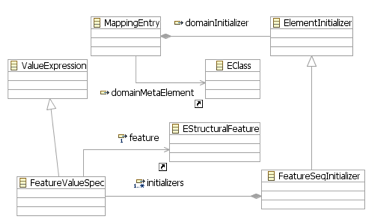
By default, if visual element encapsulating a domain element is created in the diagram, the default constructor as generated by EMF is used to initialize the newly created object. The user can define custom initialization by providing ElementInitializer. The concrete initializer currently supported is FeatureSequenceInitializer which consists of individual feature initializers. For every feature to be initialized there must be a corresponding FeatureValueSpec referencing the feature to be set, and the ValueExpression producing the initial value. The order in which FeatureValueSpec elements are evaluated and set to corresponding features is guaranteed to reflect their ordering in FeatureSequenceInitializer::initializers feature. Thus value spec expressions can safely refer to those features already initialized and reuse these values.


