Notice: this Wiki will be going read only early in 2024 and edits will no longer be possible. Please see: https://gitlab.eclipse.org/eclipsefdn/helpdesk/-/wikis/Wiki-shutdown-plan for the plan.
Creating a STEM Scenario
Contents |
Creating a STEM Scenario
Create the Project
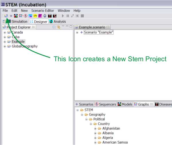
To create a new STEM project, click on the ‘new project’ icon in the command bar, or from the “New”-menu use the “New -> scenario” command.
Figure 1: Creating a New STEM Project ("ExperimentalDisease").
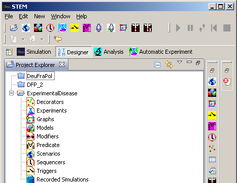
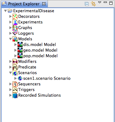
Figure 2: Project Explorer
The ‘Project’ structure thus created under the name ‘ExperimentalDisease’ contains headings for all the components that are necessary to compose a runnable scenario, including a substructure for the scenario definitions themselves.
Create a Scenario
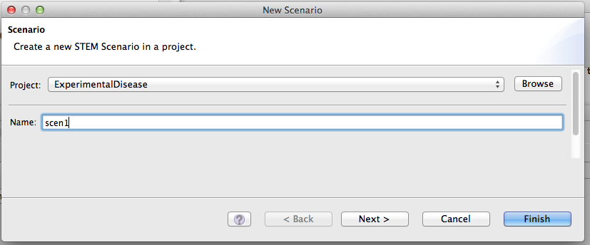
The ‚Scenario’ is the basic executable unit that can be run as an experiment. A scenario requires a number of mandatory components to be executable, while some other control elements are optional and can add extended functionality to a given basic scenario. Under the menu item “New -> scenario”, you can create a new scenario entry for the scenarios section of your new project.
Figure 3: Scenario Creation
Upon creation of the scenario, you also select the Solver algorithm you want to use.
The Finite Difference method is a simple algorithm that is useful to quickly run a simulation and verify that everything looks right.
However, for real scenarios where data is being collected for analysis, we recommend using the Runge Kutta Adaptive Step Size method because this algorithm is much more accurate.
If you use the Runge Kutta method, you also need to specify a "Relative Tolerance" factor in the disease model parameters.
The smaller this number the more accurate the calculations will be, but the simulation will also run slower. The default is 0.05 (or 5%), which we recommend lowering if possible to 0.01 or even 0.001.
It all depends how much time you can spare running a scenario.
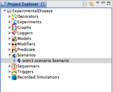
Figure 4: Project Explorer
To be made executable, the blank scenario further requires a sequencer, an infector and a nested model structure.
Add model containers for the model hierarchy
By clicking “New -> model”, you can create an empty model container.
Because we will need three different models in a nested structure, we need to create three model containers, named ‘geo’, ‘pop’ and ‘dis’ for this example.
Figure 5: Model Creation
Import graphs from the STEM framework
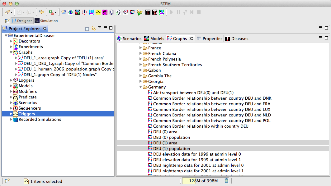
The geographical data and the population data can be imported as graphs from the STEM framework by pulling the graphs from the STEM resources section on the right into the graphs section on the left under Project Explorer. Here we use country-specific data for Germany.
Figure 6: Graph Import
Create the geography model
The bottom model in the model hierarchy is the geographic model.
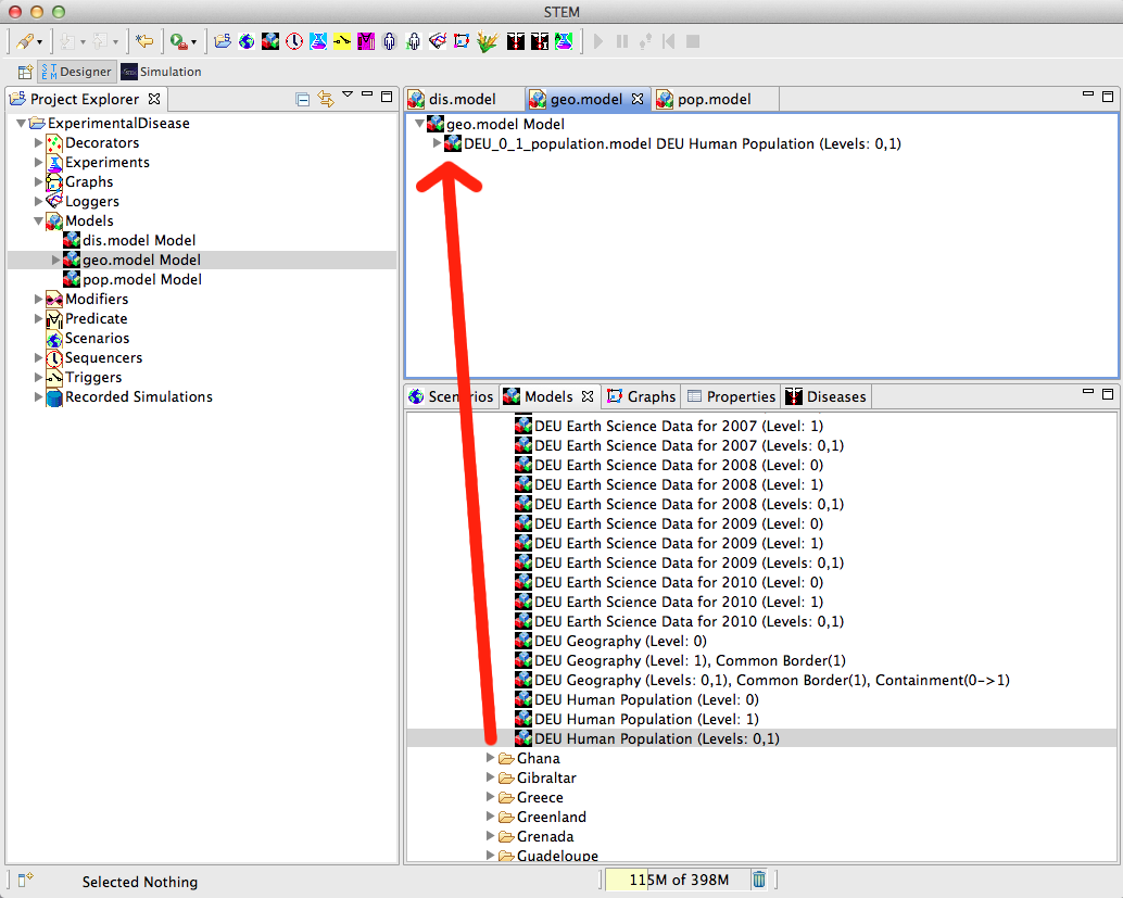
This needs to be filled with the ‘area’ graph, the ‘nodes’ graph, and the ‘Common Border relationship within country DEU’ graph.
This is done by opening the ‘geo.model’ in the Designer view (simply by double-clicking it in the Project Explorer),
and dragging the graphs into the geo.model. Saving your geo.model at this stage is probably a good idea, and can be done by hitting <ctrl S> in the Designer view of the model.
Figure 7: Equipping Models
Create the population model
The population model contains the geography model plus the population graph. It can be created by opening the pop.model in the Designer Perspective, and dragging the geo.model from the project view into the pop.model in the Designer. Add the population graph to this, and the basic population model is ready. It is possible to create more elaborate population models (e.g., multiple populations etc.), but no further specifications are not present, an automatically generated population model will be used; this is basically just a wrapper around the population data contained in the imported graph.
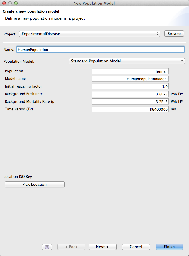
Figure 8: Population Model
Create the disease model
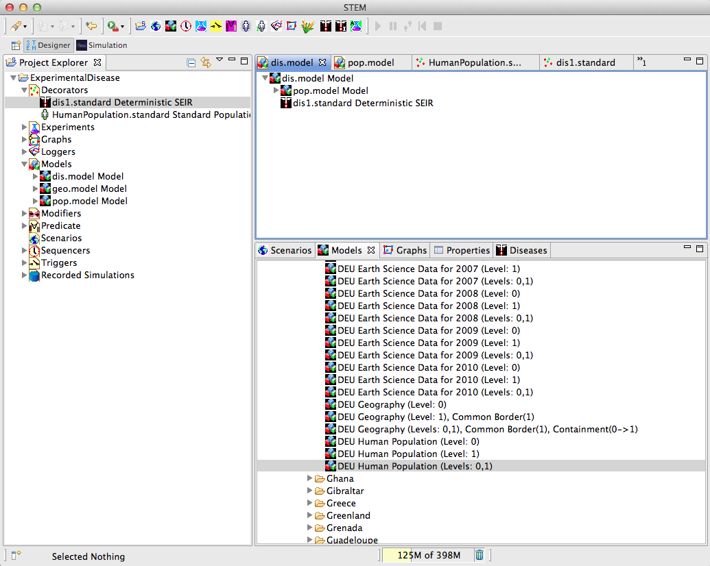
To compose the disease model, we finally also need a disease. The disease construction is accessible via the “New -> disease” command. For the sake of creating an example disease, take note that the transmission rate is set to a value larger than zero, and also note that the name of this disease will be required to initialize the infector later on in the scenario construction. The newly defined disease appears in the ‘Decorators’ section of the Project Explorer, and this is also where the infector will appear when it is created. For this demonstration, we choose a DeterministicSEIRDiseaseModelImpl. with a Transmission Rate of 1.0, an Infectious Recovery rate of 0.5, Immunity Loss Rate of 0.3, and an Incubation Rate of 0.3
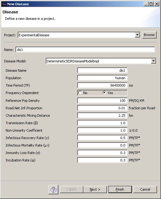
Figure 9: Disease Creation
After creating a disease, you will be able to inspect the properties of the disease in the ‘Properties’ tab of the Resources section of the Designer View. Make sure that all parameters have been entered correctly, e.g., that you have a Transmission Rate larger than Zero. You can change the values of properties in this tab by simply editing them, and saving them by hitting <ctrl-S> in the Designer View again.
To create the disease model, proceed just as before by pulling the pop.model and the disease from the Project Explorer onto the empty dis.model in the Designer View, and save the disease model with <ctrl-S> to update the project.
Create an Infector
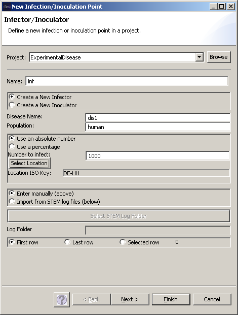
The command “New -> infector” allows you to create an infector. An essential information for the infector is the disease to be linked to this infector, thus ‘Disease Name’ must correctly spell out the name of the disease defined earlier. Furthermore, the geographical location must be specified (under the ‘Select Location’ button), in this case Hamburg as one of the 41 nodes in the geographic model for Germany.
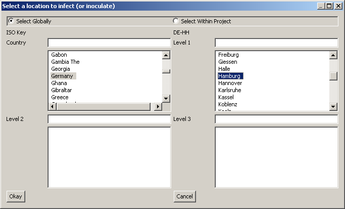
Figure 12: ISO Key selection for Infector
Create a Sequencer
Any scenario will also need a sequencer to be runnable. Under “New->Sequential Sequencer” you can create a sequencer, that specifies the temporal increments upon which the evolution of your scenario will be based. For the sake of brevity, the screenshot is omitted here.
Equip the Scenario
With a sequencer, an infector, and a nested model hierarchy at our disposal, we can now proceed to equip the scenario. This is done again by simply dragging the components from the Project Explorer onto the scenario heading in the Designer View. The asterisk preceding the scenario name in the tab header of the Designer View indicates unsaved work. Saving the scenario will update the scenario hierarchy in the Project Explorer.
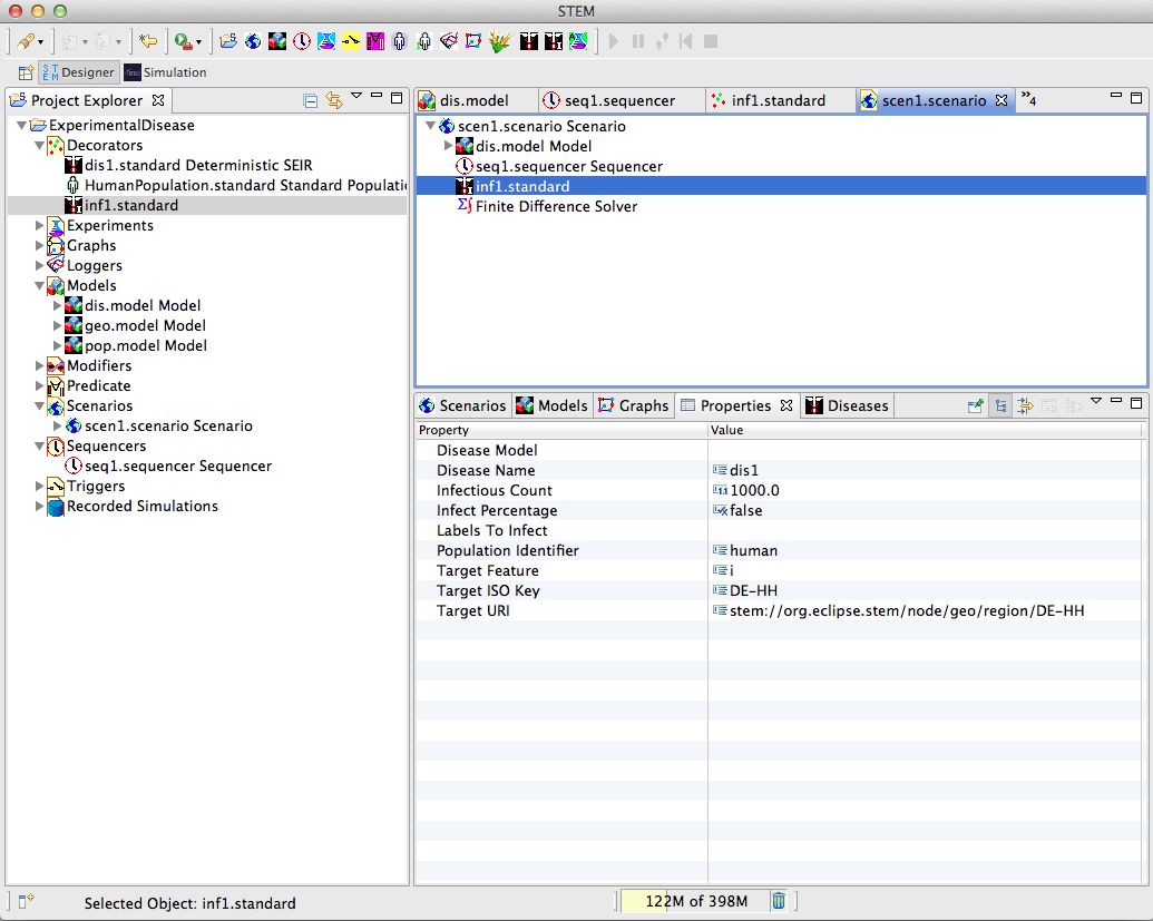
Figure 13: Scenario Completion
Run the Scenario
Right-clicking on the scenario heading and selecting the green triangle icon for “run”, you can now run the scenario and observe the progression of the disease given the selected parameters.


