Notice: This Wiki is now read only and edits are no longer possible. Please see: https://gitlab.eclipse.org/eclipsefdn/helpdesk/-/wikis/Wiki-shutdown-plan for the plan.
STP/IM Component/STP Internal Model Discussion
Contents
Introduction
This page aims to serve as a starting point for a discussion on the internal representation of artefacts in Eclipse STP. It is envisaged that several editors will be used separately or in coordination in order to create SOA entities and architectures. Examples of such editors include
- SCA Editor
- JBI Editor
- BPMN editor
- BPEL editor
Each editor uses its own internal (meta-)model corresponding to its underlying foundation (SCA, BPMN, BPEL, JBI etc). In order to "move" data from editor A to editor B, a transformation bridge should be created for making the conversion between the meta-model of A and the meta-model of B. It might be useful to have a consistent representation of the least common denominator of the different editors (rather of the architectural and functional information created with the different editors). Each editor could "silently" put data in this intermediate meta-model as well as read data from this meta-model upon activation. This would ensure that if something is created with one editor, at least some of the data would be available to all other editors (automatically). The advantage of this approach (presented below outlined in the Common STP Meta-Model sub-section) over the direct transformation approach stems from the fact that fewer transformations must be written. For n editors we will have a maximum of n transformations instead of a maximum of n2 transformations.
NOTE: Clearly all transformations would have the effect of losing semantics and information from the source model to the target one. The simpler the intermediate model is, the more information is lost in the transformations. However, if we can strike a good balance in designing the intermediate meta-model, we could transport a good amount of information across editors with relatively little effort. In order to achieve a more complete transformation for a particular pair of editors, such as generation of Java from BPEL, it is clear that a 1 to 1 direct transformation must be performed. So it is envisaged that the two approaches (a limited set of direct transformations and a large set of transformations using an intermediary) would have to coexist.
EXAMPLE: A sample scenario showing the meta-model usage is available. The scenario goes through several steps of creating a basic SOA system using simplified Eclipse STP editors that use the intermediate meta-model.
The remainder of this page presents an initial meta-model created by INRIA (France) and Engineering (Italy) in order to fuel discussions around the intermediary approach to preserving model consistency in STP. Other possible approaches to preserving model consistency are also presented on this page, the aim being to create a common ground for discussions around this theme. Lastly, this page presents a a discussion of SCA and JBI followed by an example of a conceptual mapping between the two.
Consistent Representation in STP
As mentioned above, it is desirable that there be a consistent representation of the main artefacts created or used in Eclipse STP. A Service for instance should be available to architects and developers using either editor / technology. In particular, a service appearing in the logical architecture designed with SCA should be rendered "accessible" in the JBI editor or indeed in the BPMN or BPEL editors. It should be "same service" that is used everywhere across STP. We should aim to have minimum redundancy in the design process.
There are several approaches that can be used to ensure inter-model consistency. They are outlined in the following sub-sections.
Direct 1 to 1 Model Transformation
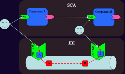
Each STP user designs / develops using their favourite editor. Transformation capabilities are offered for conversions between models as soon as a new editor is used. Several common concepts in SCA and JBI for instance can be mapped as illustrated in the figure below.
Common Service Repository
This would imply that all services, regardless of the editor they were first created with, are available throughout Eclipse STP via a repository explorer. All editors must therefore make sure they "add" the new service to the repository. A possible disadvantage of this solution is the service interactions (e.g. orchestrations) could be lost. [Oisin, do you want to add more info here?]
Common STP Meta-Model
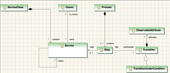
This would be a hybrid approach in which a common meta-model is used to hold the information that is more or less common across editors / technologies. Transformations from all individual editor models must be performed to obtain this "intermediate" representation (ecore2ecore with ATL). This approach is also similar to the service-repository approach, however it allows the addition of more information to be stored.
The figure below shows a first draft of the intermediate meta-model created by INRIA and Engineering. This will most likely need more work, please feel free to send your comments!
Thanks to Stéphane Drapeau (Obeo) and Valerio Schiavoni (INRIA) for pointing out that an ongoing effort to bridge different SOA-related specifications is presented at [1] (this could also provide inspiration for the STP internal meta-model).
Internal Models (e.g. SCA and JBI)
This subsection presents a very simplified and limited subset of the (meta-)models for SCA and JBI.
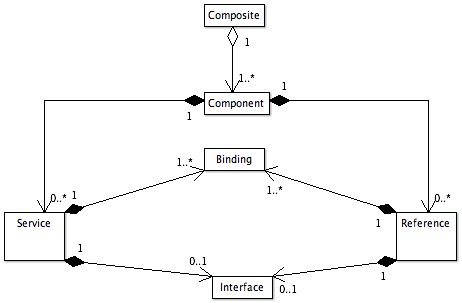
In SCA, we have components that may be contained in composites. A component can have any number of services that it can offer. In addition, a component may depend on other components and this dependency is indicated by references. Each service and reference can have an interface and one or more bindings corresponding to the supported communication protocols. Note that in SCA, the focus is on a logical architecture, with concerns such as bindings being secondary. We can have SCA diagrams that contain components / composites, each exposing services and references, and we can add information about bindings later on in the design process.
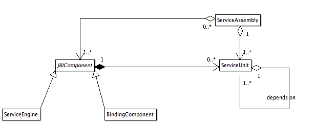
On the contrary, as seen above, in JBI the focus is more on the technological aspects of the bus. The central entity is the JBI Component which can be of two types (Binding Component or Service Engine). Each such component can be installed on the bus. "Logical" artefacts such as services to be exposed on the bus will be packaged into service units and deployed onto the JBI components which will end up containing a collection of such artefacts. To make deployment easier and to facilitate the expression of dependencies, service units can be grouped together into service assemblies that can be deployed as a whole. Therefore in JBI, the focus is reversed from that in SCA, and it is centred on the "bindings" and the bus services, with the logical services coming secondary, in a way.
Sample SCA to JBI Conceptual Transformation
The smiley faces represent service clients. The top half of the figure illustrates a basic SCA diagram. Component A offers a service through a WS-type binding and requires a component of type B. Component B offers a service through its JMS binding. The wire between them illustrates that A calls B. The bottom half of the figure is an illustration of a JBI configuration. As mentioned in the discussion above, the roles are inverted, i.e. the focus is here on the bindings and how the services are "deployed" onto them. The fact that A calls be is something that in JBI cannot be easily expressed. There are ways to suggest this by expressing the dependency between these components but this is something that is not compulsory in JBI. Additionally, the dependency specification does not have the same semantics as the wire in SCA. It is more a way to express that "if A is deployed, B must be there too". Indeed, if more interactions with A and B (and maybe other components) are going to be described in SCA, we would not be able to see them by just looking at the JBI deployment descriptor. The only way to "see" the interactions described by wires in SCA is to observe the message exchanges on the JBI bus (DeliveryChannel / MessageExchange interceptors - this type of interception is illustrated with a red dotted line in the figure).
Comments
I would go for the third option (common meta-model) perhaps in combination with some 1 to 1 transformations. --Adrian.mos.inria.fr 11:56, 21 August 2007 (EDT)


